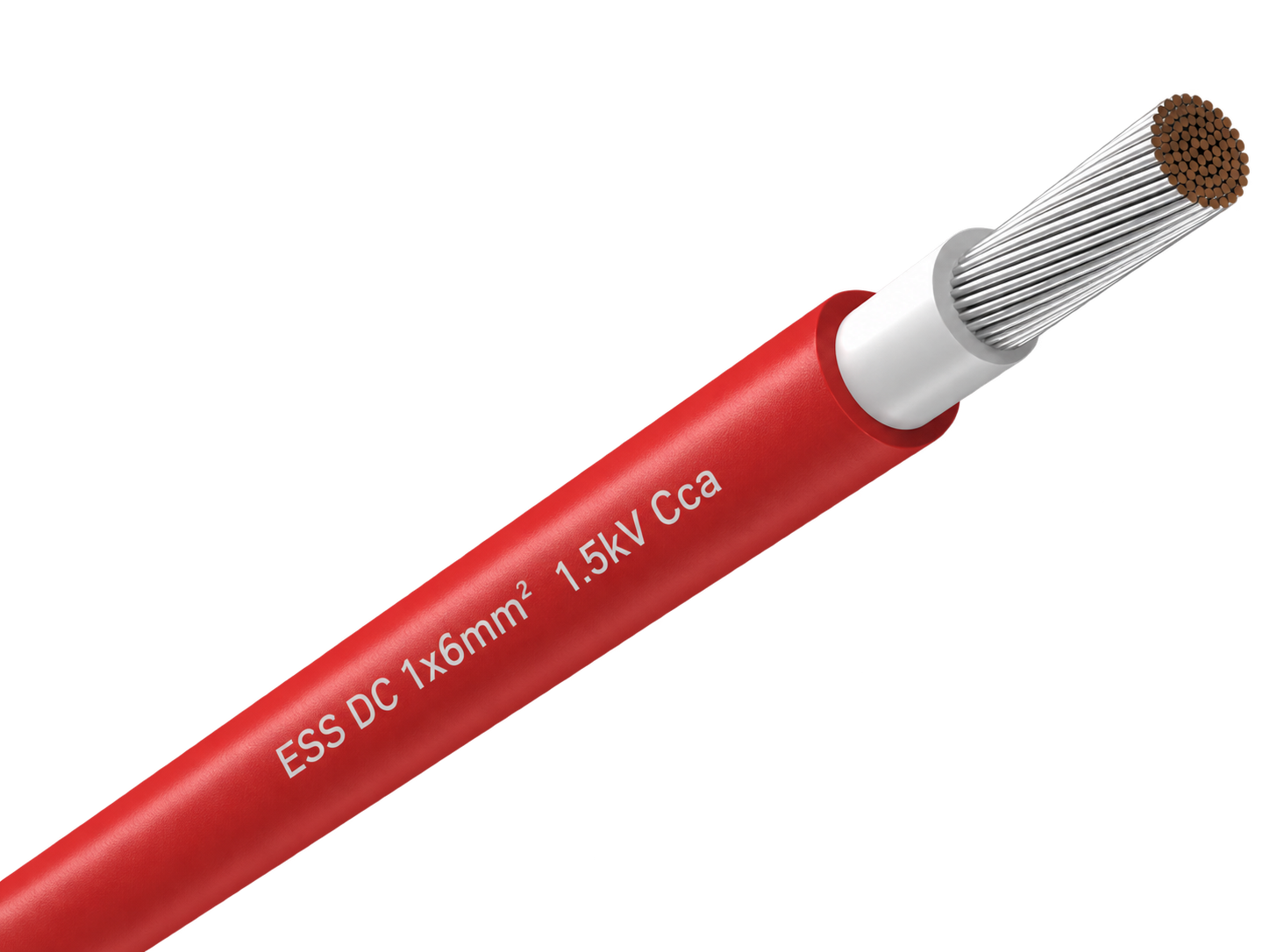
H1Z2Z2-K Nylon-Barrier Rodent-Resistant Solar Cable
H1Z2Z2-K 1.5 kV DC solar cable with a nylon barrier beneath the outer sheath for PV routes that need a non-metallic physical defence against rodent damage.

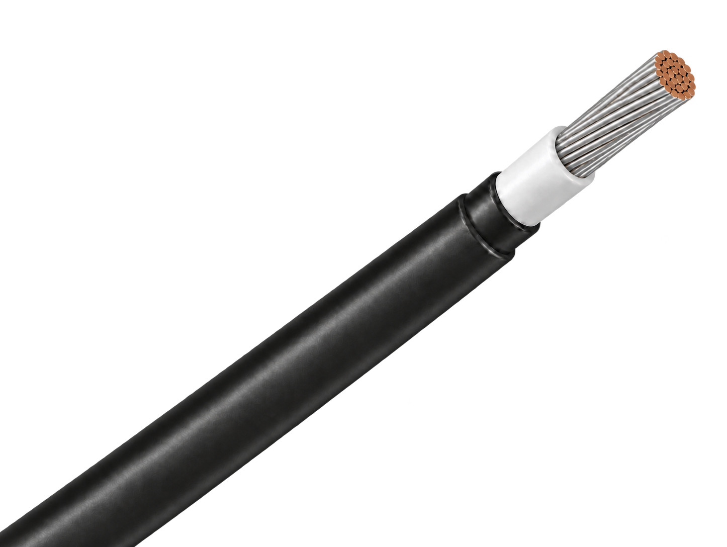
H1Z2Z2-K 1.5 kV DC solar cable with a nylon barrier beneath the outer sheath for PV routes that need a non-metallic physical defence against rodent damage.
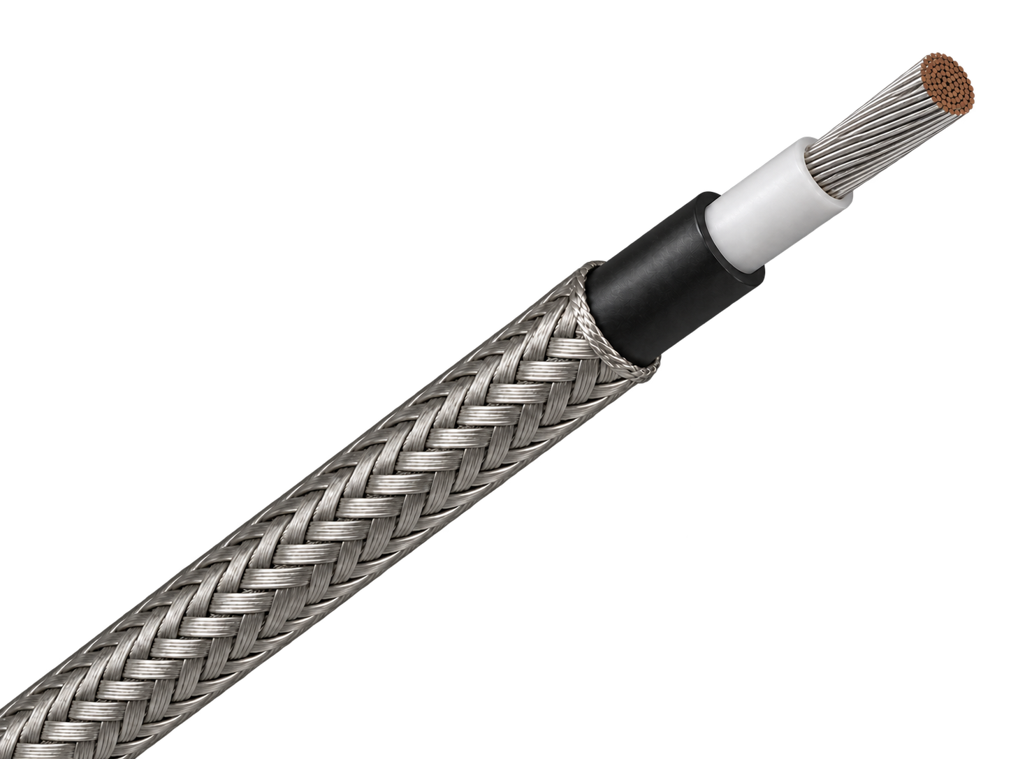
H1Z2Z2-K 1.5 kV DC solar cable with external steel-wire armour for fixed PV routes exposed to severe rodent activity or mechanical damage.
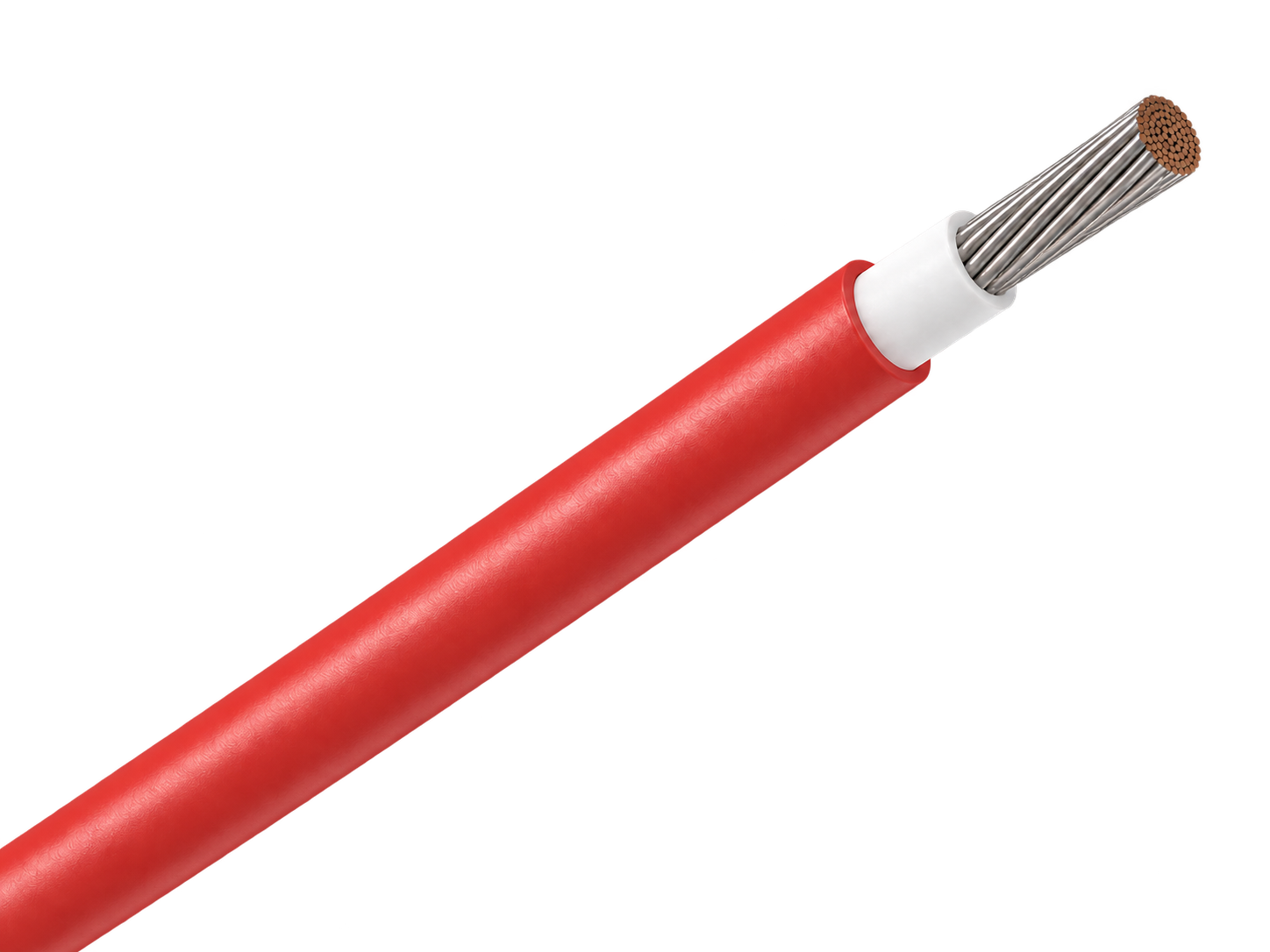
H1Z2Z2-K 1.5 kV DC solar cable with a capsaicin-based rodent-deterrent sheath for PV routes where chemical protection is preferred over added armour.
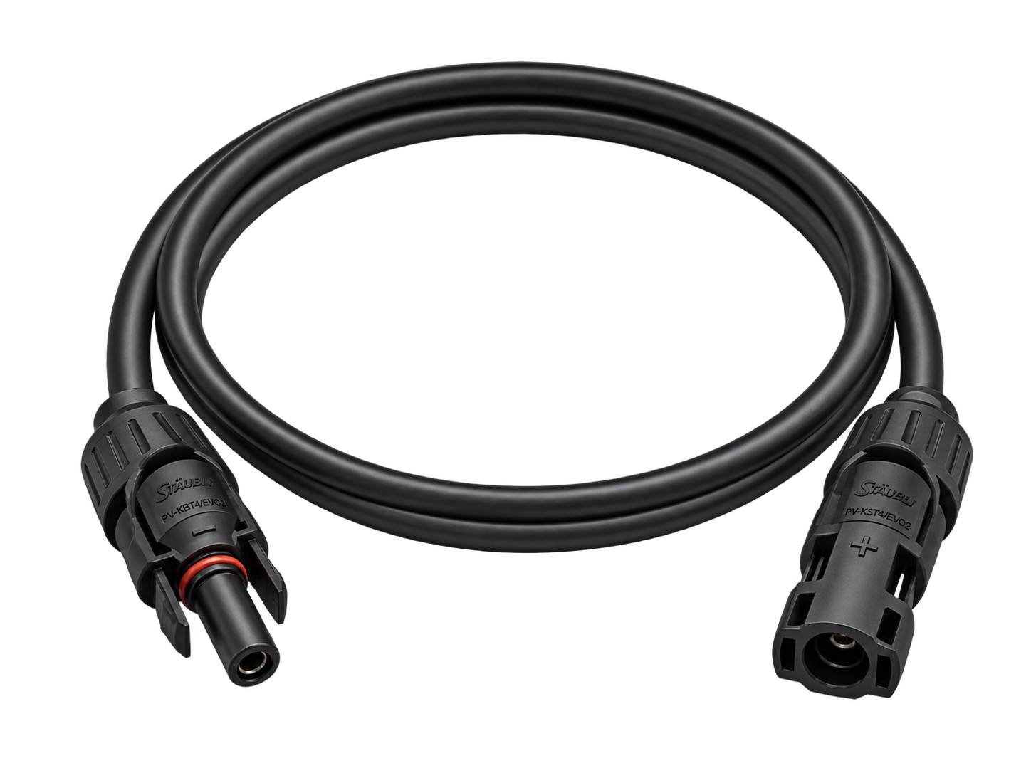
Factory-terminated PV extension cable for controlled module, string and combiner-box connections.
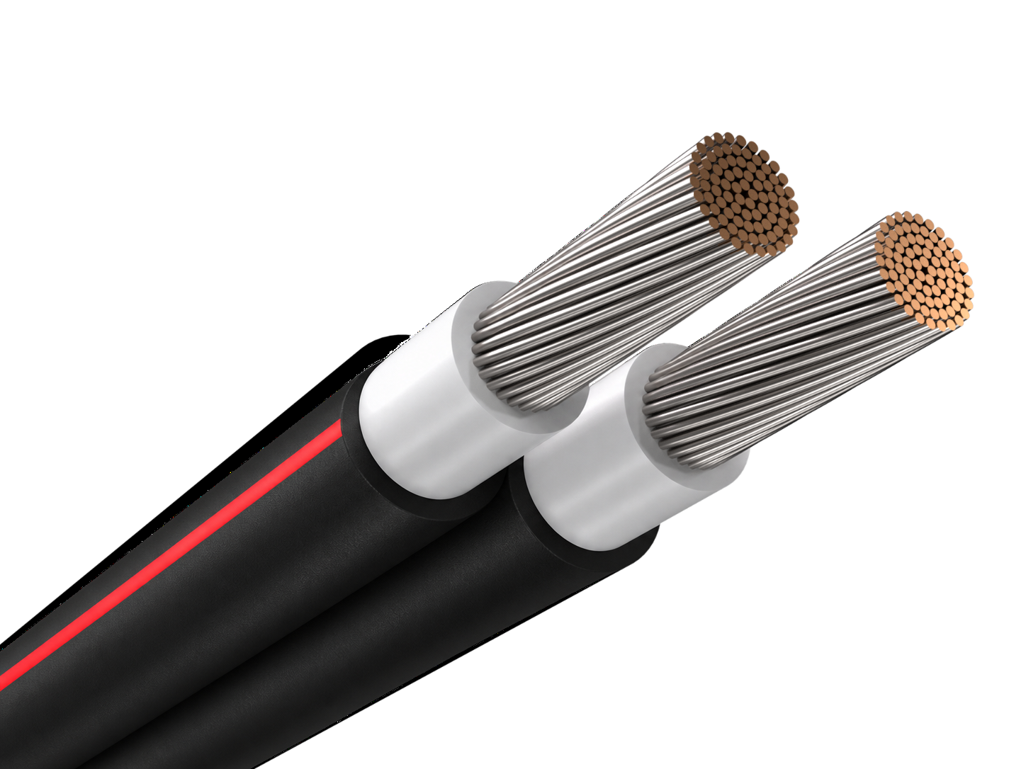
Joined twin PV cable for orderly positive and negative string routing beneath solar modules.
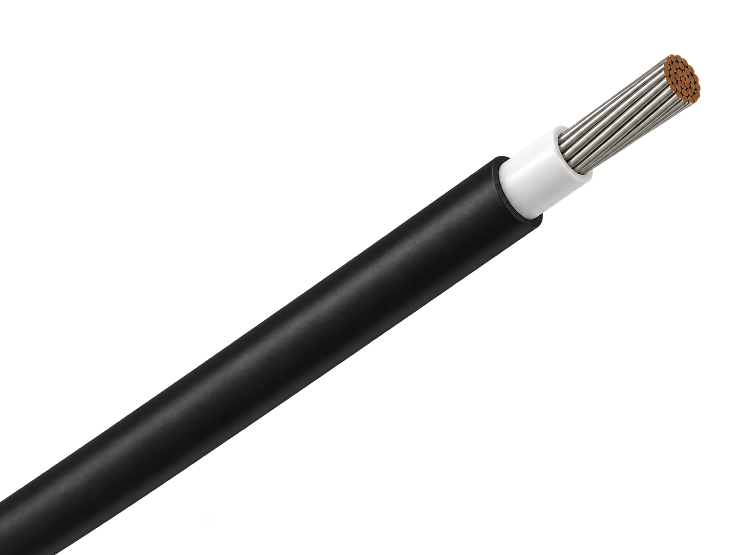
Single-core PV cable for reliable DC wiring across rooftop and ground-mounted solar arrays.
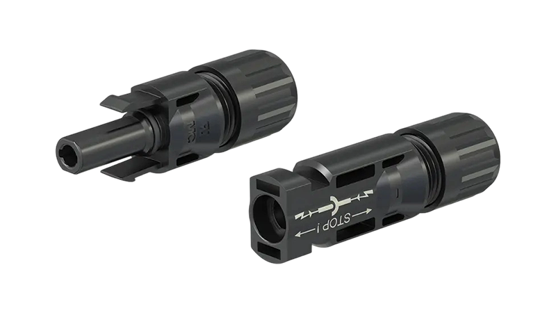
Original 4 mm DC PV connector for field-assembled module, string and extension-cable connections.
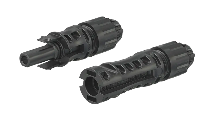
1500 V DC Original Stäubli PV connector for high-current string, extension and equipment connections.
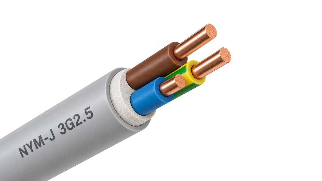
PVC-sheathed 300/500 V cable for fixed power and lighting circuits inside buildings and panels.
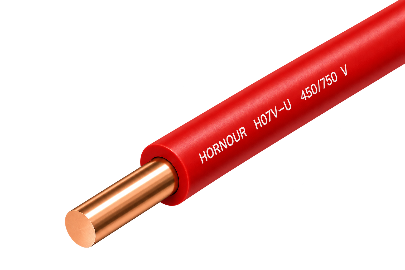
Solid 450/750 V PVC wire for stable fixed circuits in protected conduit and building installations.
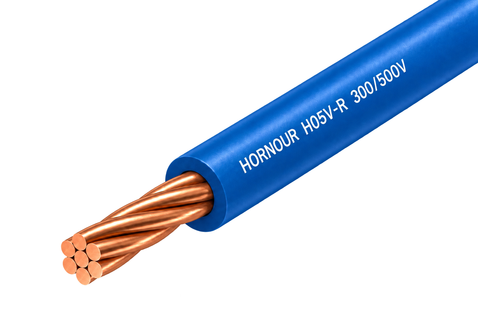
Class 2 stranded 300/500 V PVC wire for fixed equipment and panel routes needing moderate flexibility.
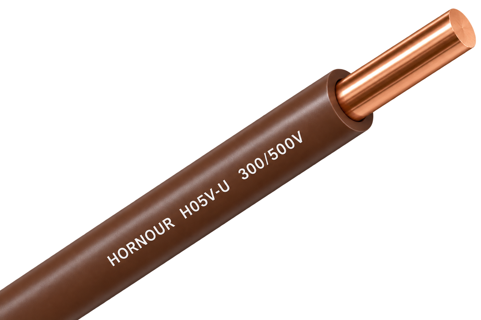
Solid 300/500 V PVC wire for simple, stable fixed connections inside protected equipment and conduit.
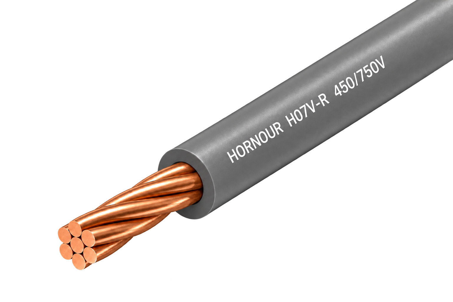
Class 2 stranded 450/750 V PVC wire for protected fixed routes requiring easier pulling and forming.
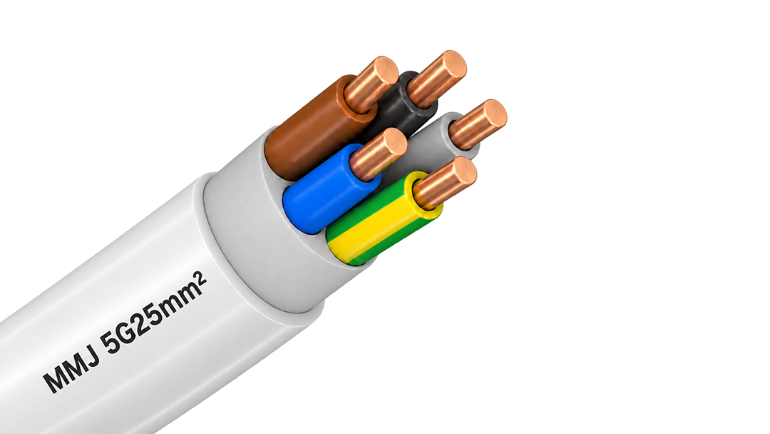
300/500 V PVC-sheathed cable for fixed surface and flush-mounted installations in Finnish building wiring.
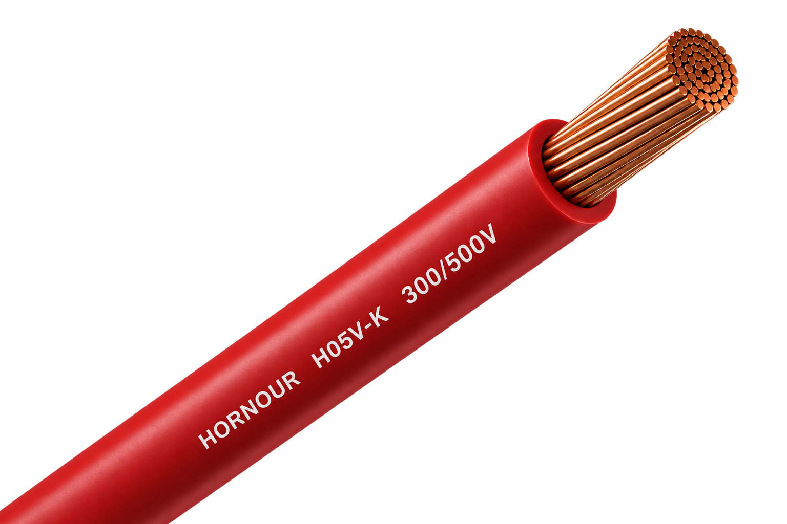
Flexible 300/500 V PVC wire for compact equipment, switchgear and control-panel connections.
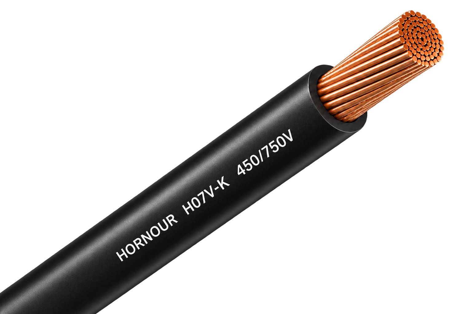
Flexible 450/750 V PVC wire for protected conduit, panel and grounding connections.
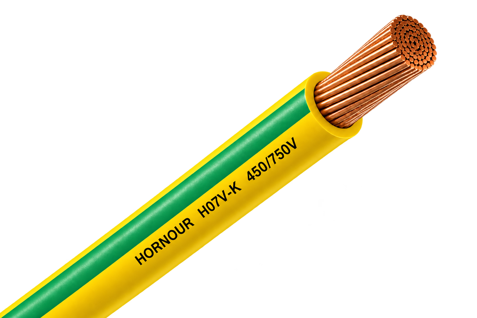
Green/yellow H07V-K Class 5 copper wire for protective-earth and equipotential-bonding connections in PV, ESS and electrical installations.
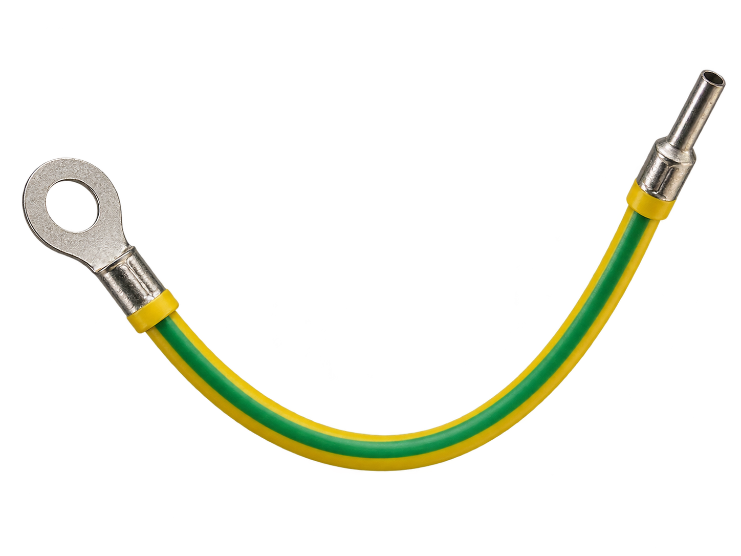
Green/yellow H07V-K grounding lead with factory-crimped ring / OT terminal for ready-to-install earthing and bonding connections.
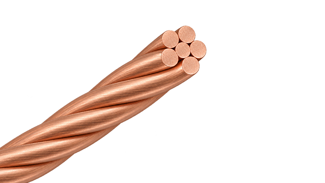
Bare Class 2 stranded copper conductor for earthing and equipotential bonding, available in 16–120 mm².
H1Z2Z2-K 1.5 kV DC solar cable with a nylon barrier beneath the outer sheath for PV routes that need a non-metallic physical defence against rodent damage.
H1Z2Z2-K 1.5 kV DC solar cable with external steel-wire armour for fixed PV routes exposed to severe rodent activity or mechanical damage.
H1Z2Z2-K 1.5 kV DC solar cable with a capsaicin-based rodent-deterrent sheath for PV routes where chemical protection is preferred over added armour.
Factory-terminated PV extension cable for controlled module, string and combiner-box connections.
Joined twin PV cable for orderly positive and negative string routing beneath solar modules.
Single-core PV cable for reliable DC wiring across rooftop and ground-mounted solar arrays.
Green/yellow H07V-K Class 5 copper wire for protective-earth and equipotential-bonding connections in PV, ESS and electrical installations.
Green/yellow H07V-K grounding lead with factory-crimped ring / OT terminal for ready-to-install earthing and bonding connections.
Bare Class 2 stranded copper conductor for earthing and equipotential bonding, available in 16–120 mm².
PVC-sheathed 300/500 V cable for fixed power and lighting circuits inside buildings and panels.
Solid 450/750 V PVC wire for stable fixed circuits in protected conduit and building installations.
Class 2 stranded 300/500 V PVC wire for fixed equipment and panel routes needing moderate flexibility.
Solid 300/500 V PVC wire for simple, stable fixed connections inside protected equipment and conduit.
Class 2 stranded 450/750 V PVC wire for protected fixed routes requiring easier pulling and forming.
300/500 V PVC-sheathed cable for fixed surface and flush-mounted installations in Finnish building wiring.
Flexible 300/500 V PVC wire for compact equipment, switchgear and control-panel connections.
Flexible 450/750 V PVC wire for protected conduit, panel and grounding connections.
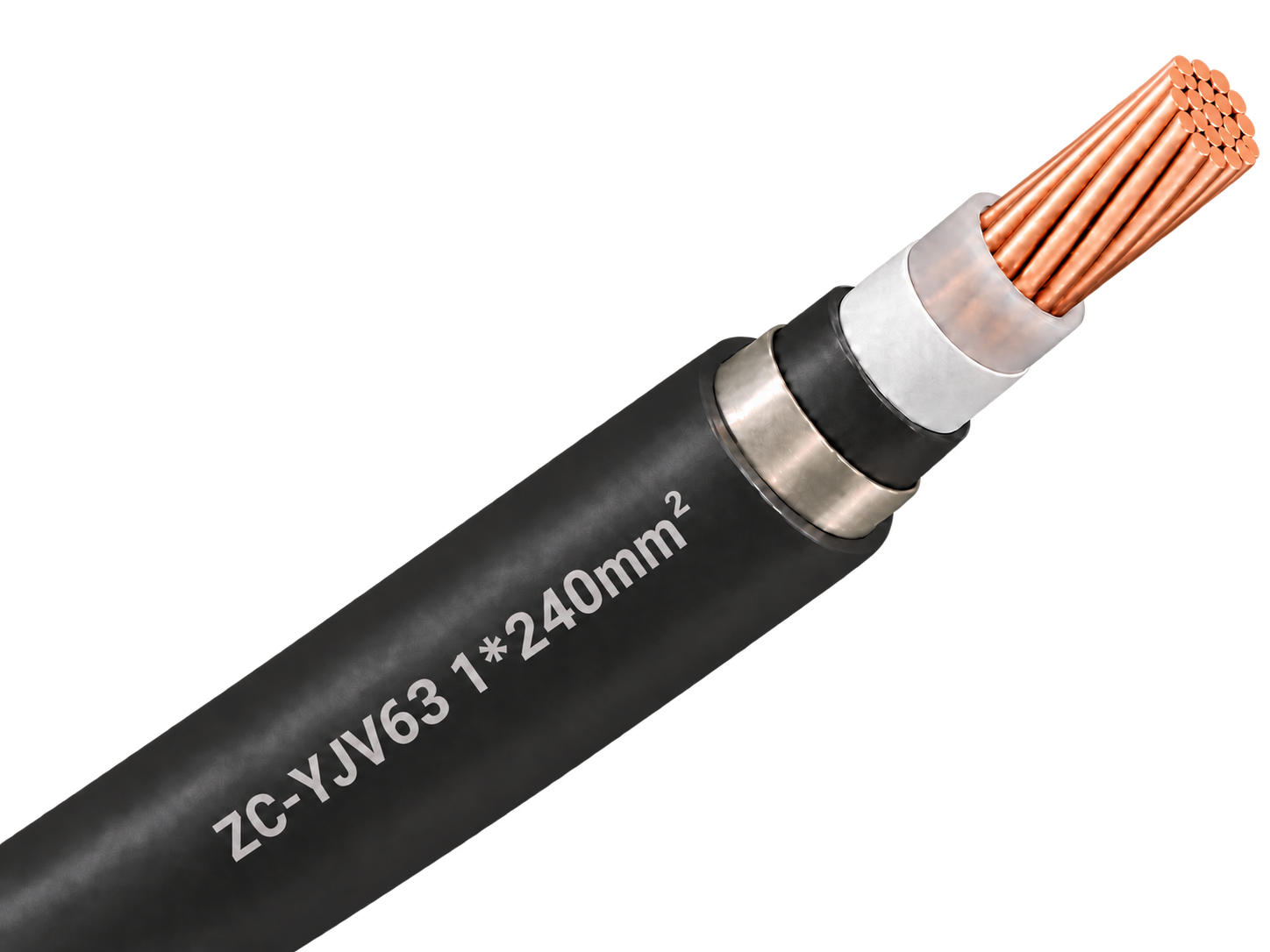
Single-core 1.8/3 kV copper XLPE cable with non-magnetic stainless-steel tape armour, PVC sheath and Category C flame-retardant construction for protected fixed power routes.
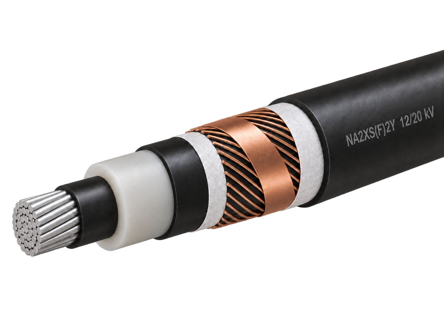
Aluminium XLPE medium-voltage cable with longitudinal water blocking for fixed distribution networks.
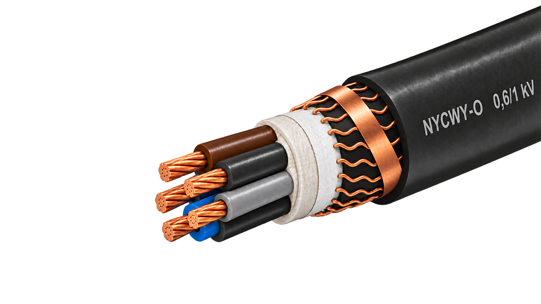
0.6/1 kV copper cable with a wave-laid concentric conductor for fixed distribution and service routes.
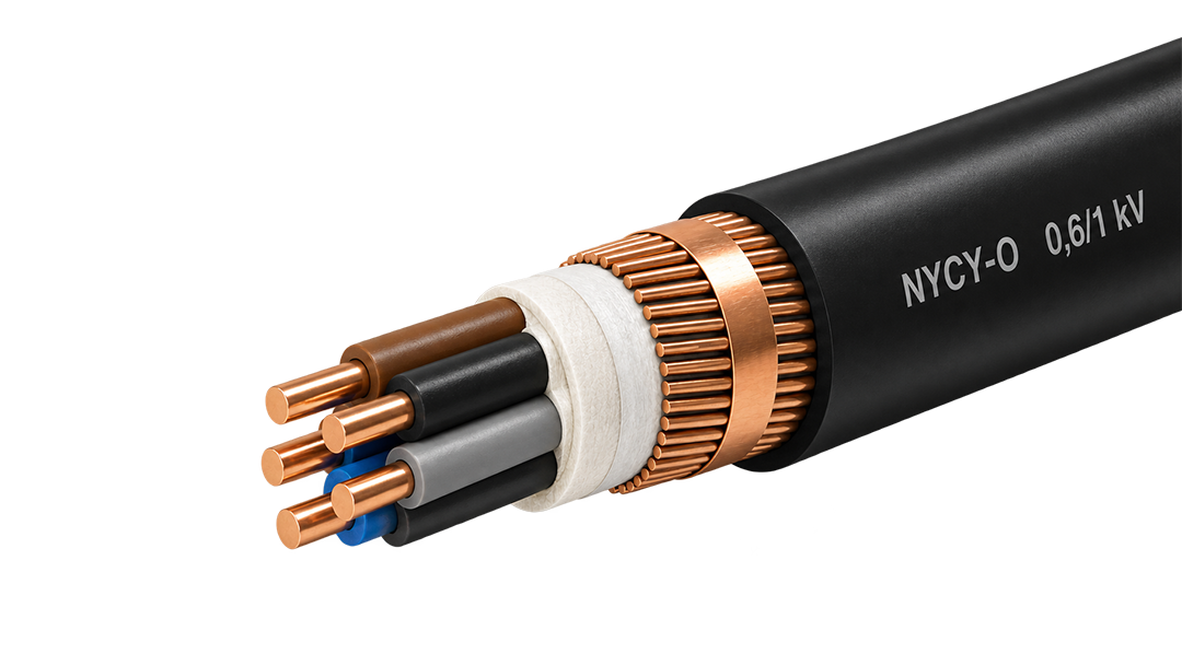
0.6/1 kV copper power cable with a concentric copper layer for service and distribution circuits.
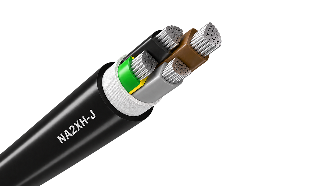
Aluminium halogen-free 0.6/1 kV cable for fire-conscious fixed distribution and long feeders.
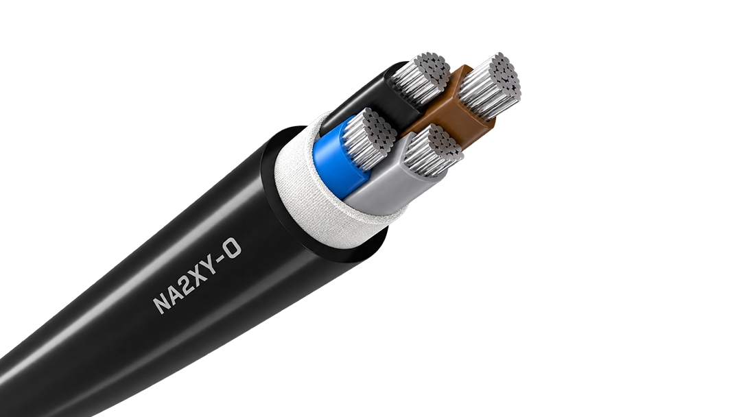
Aluminium XLPE power cable for economical fixed distribution, available in 0.6/1 kV and 1.8/3 kV constructions for long outdoor and buried routes.
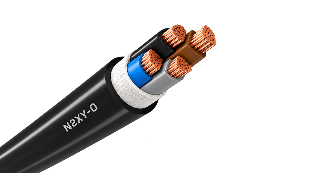
Copper XLPE 0.6/1 kV cable for demanding fixed feeders, outdoor routes and power distribution.
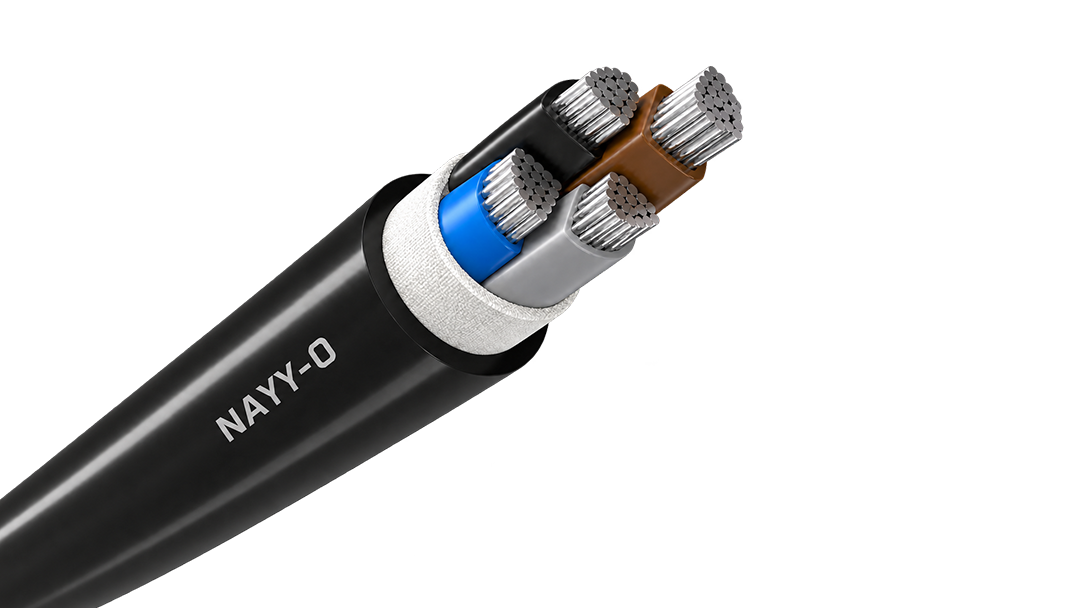
Aluminium 0.6/1 kV PVC cable for cost-conscious fixed distribution and long feeder routes.
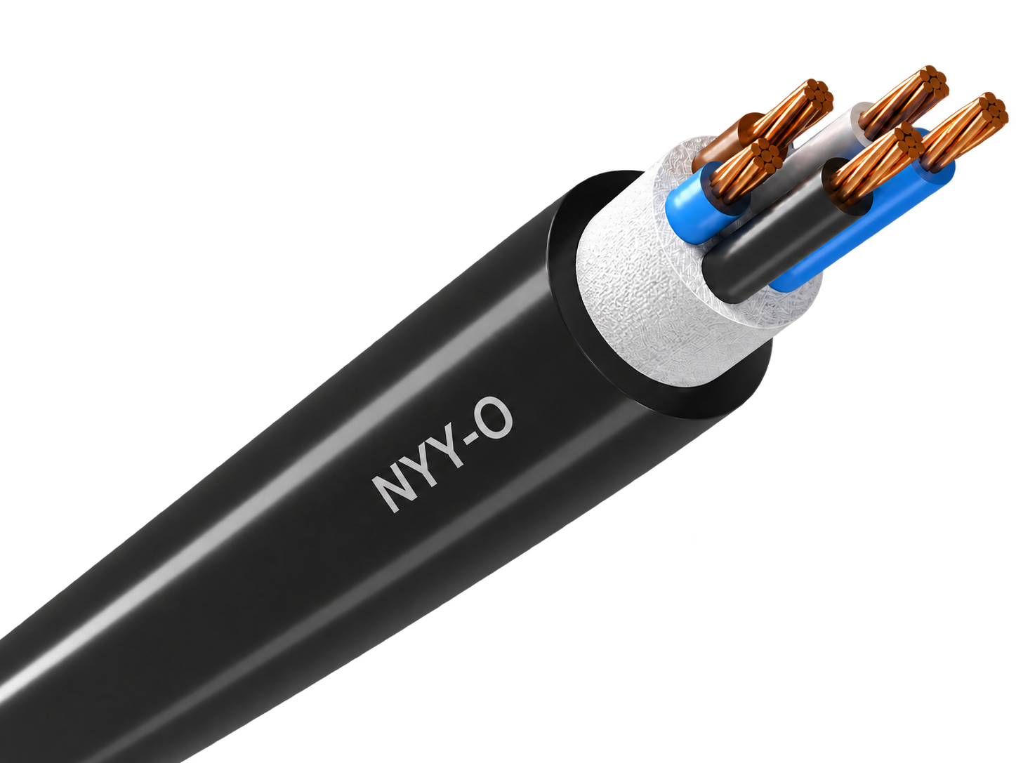
Robust 0.6/1 kV copper cable for economical fixed power distribution indoors, outdoors and underground.
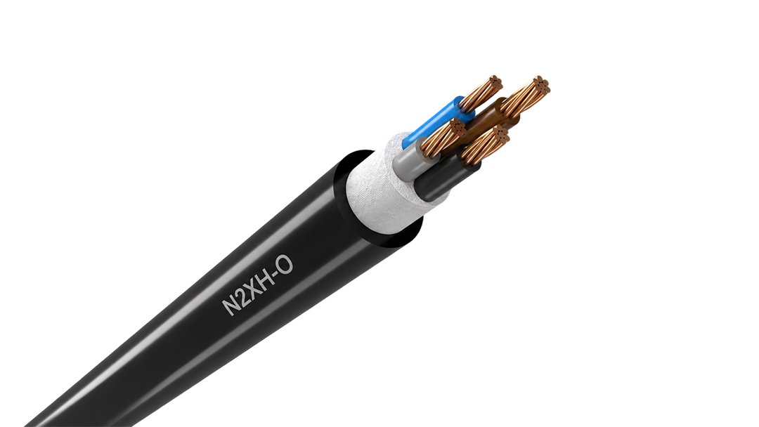
Low-smoke halogen-free 0.6/1 kV cable for fixed distribution in occupied and critical buildings.

hot search


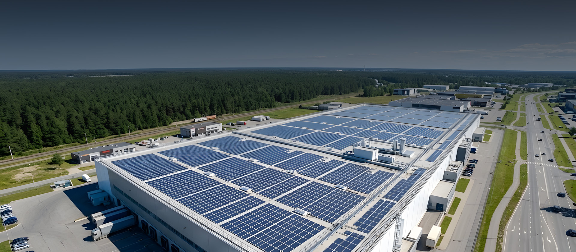
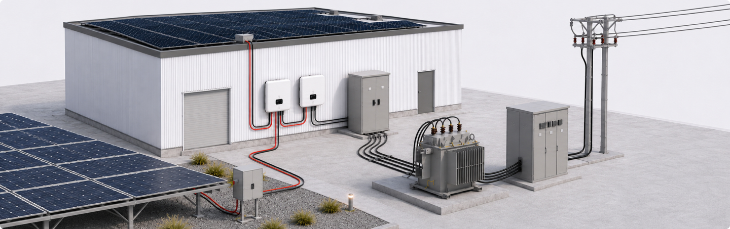
Cables for DC generation, LV distribution, transformer connections and MV collection in commercial rooftop and utility-scale photovoltaic installations.
Solar Cable
PV Extension
Power Cable LV
Power Cable MV
Single-core PV cable for reliable DC wiring across rooftop and ground-mounted solar arrays.

UV & Ozone
Resistant

-40 ℃ ~ +90 ℃
Temperature Range

25+ Years
Service Life
| Voltage Rating | 1500 V DC |
| Conductor | Tinned copper, Class 5 |
| Insulation | XLPO |
| Sheath | XLPO |
| CPR Classification | B2ca to Eca |
| Applications | PV strings, inverter connection |
Factory-terminated PV extension cable for controlled module, string and combiner-box connections.

UV & Ozone
Resistant

-40 ℃ ~ +90 ℃
Temperature Range

25+ Years
Service Life
| Voltage Rating | 1500 V DC |
| Conductor | Tinned copper, Class 5 |
| Insulation | XLPO |
| Sheath | XLPO |
| Base Cable CPR | Dca-s1a,d1,a1 |
| Applications | PV strings, inverter connection |
Aluminium 0.6/1 kV PVC cable for cost-conscious fixed distribution and long feeder routes.

Direct Burial Installation

Lightweight Aluminium for Long Feeders

Flame Retardant · IEC/EN 60332-1-2
| Voltage Rating | 0.6/1 kV |
| Conductor | Aluminium, Class 1 / Class 2 |
| Insulation | PVC |
| Outer Sheath | PVC |
| Max. Conductor Temp. | +70 °C |
| Standard | IEC 60502-1 / VDE 0276-603 |
Aluminium XLPE medium-voltage cable with longitudinal water blocking for fixed distribution networks.

Longitudinal Water Blocking

Water · Air · Soil Installation

High Mechanical Stress Resistant
| Voltage Rating | 6/10 · 12/20 · 18/30 kV |
| Conductor | Aluminium, Class 2 |
| Insulation | XLPE |
| Screen | Copper wires with copper spiral |
| Outer Sheath | PE |
| Standard | DIN VDE 0276-620 / IEC 60502-2 |
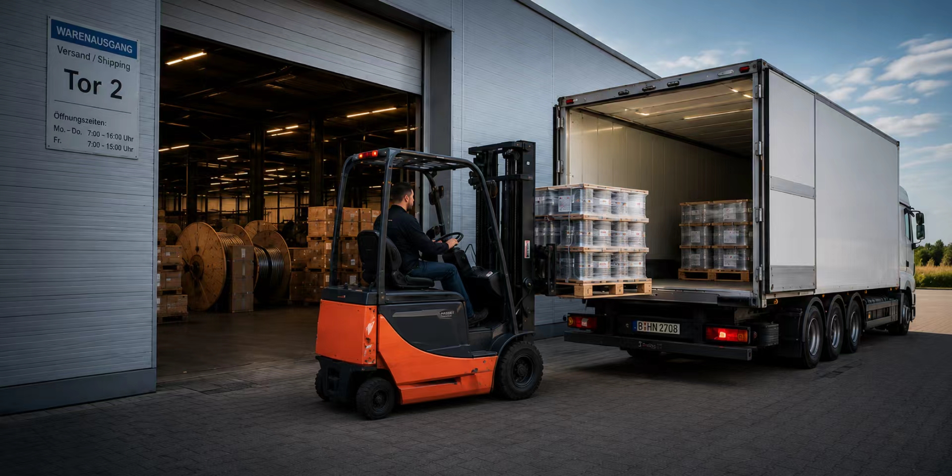


Typical cable arrangements for commercial rooftop and utility-scale PV projects, from PV string connections to LV distribution and MV collection.
| Project Configuration | Connection | Cable System | Typical Installation |
|---|---|---|---|
| Commercial Rooftop PV | PV module strings → string inverter | Solar DC Cable | Rooftop / cable tray |
| Commercial Rooftop PV | String inverter → LV distribution board | LV Power Cable | Rooftop / electrical room |
| Utility-Scale PV – DC Side | PV strings / combiner boxes → inverter | Solar DC Cable | PV field / cable tray / duct |
| Utility-Scale PV – LV Side | Inverter → step-up transformer | LV Power Cable | Inverter / transformer station |
| Utility-Scale PV – MV Collection | Step-up transformer → MV switchgear / substation | MV Power Cable | Cable trench / duct / underground |
| Commercial & Utility PV – Earthing | Module structures / electrical equipment → earthing network | Grounding Cable / Conductor | Rooftop / PV field / equipment area |
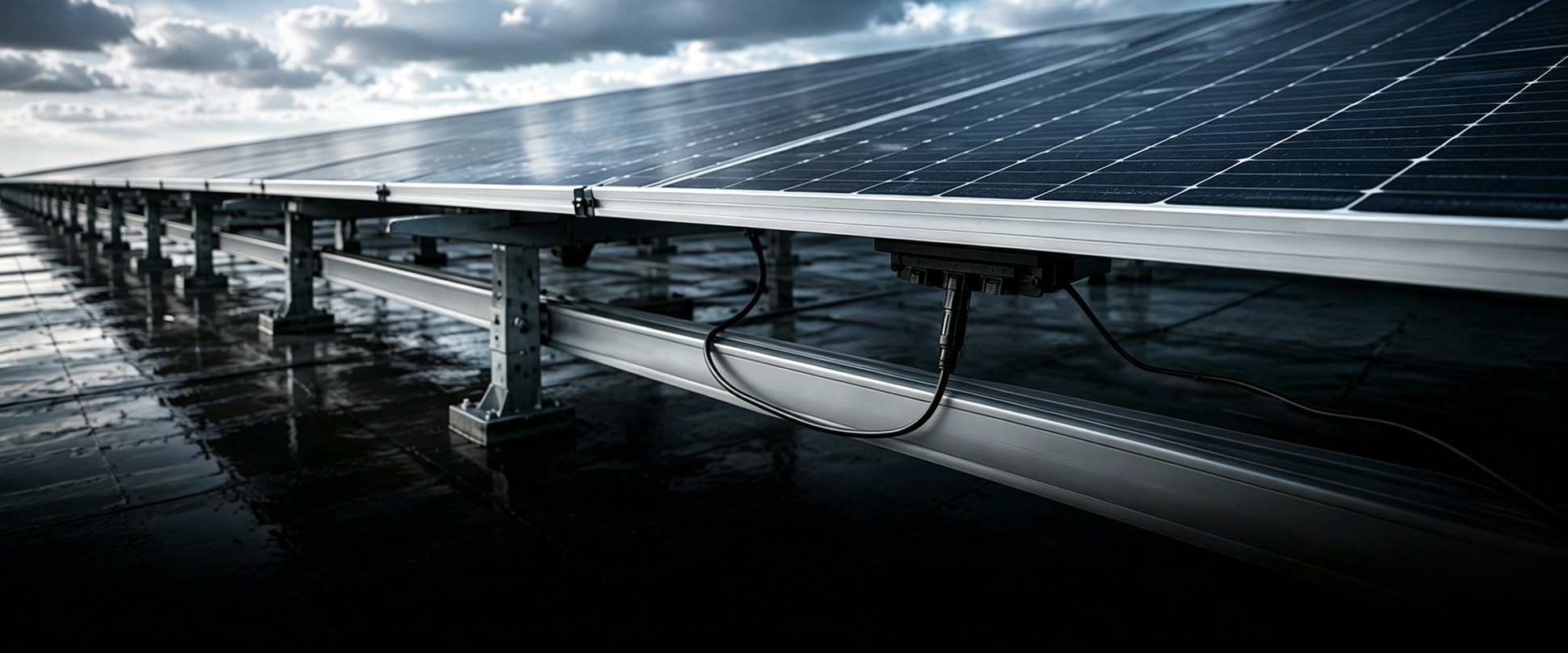
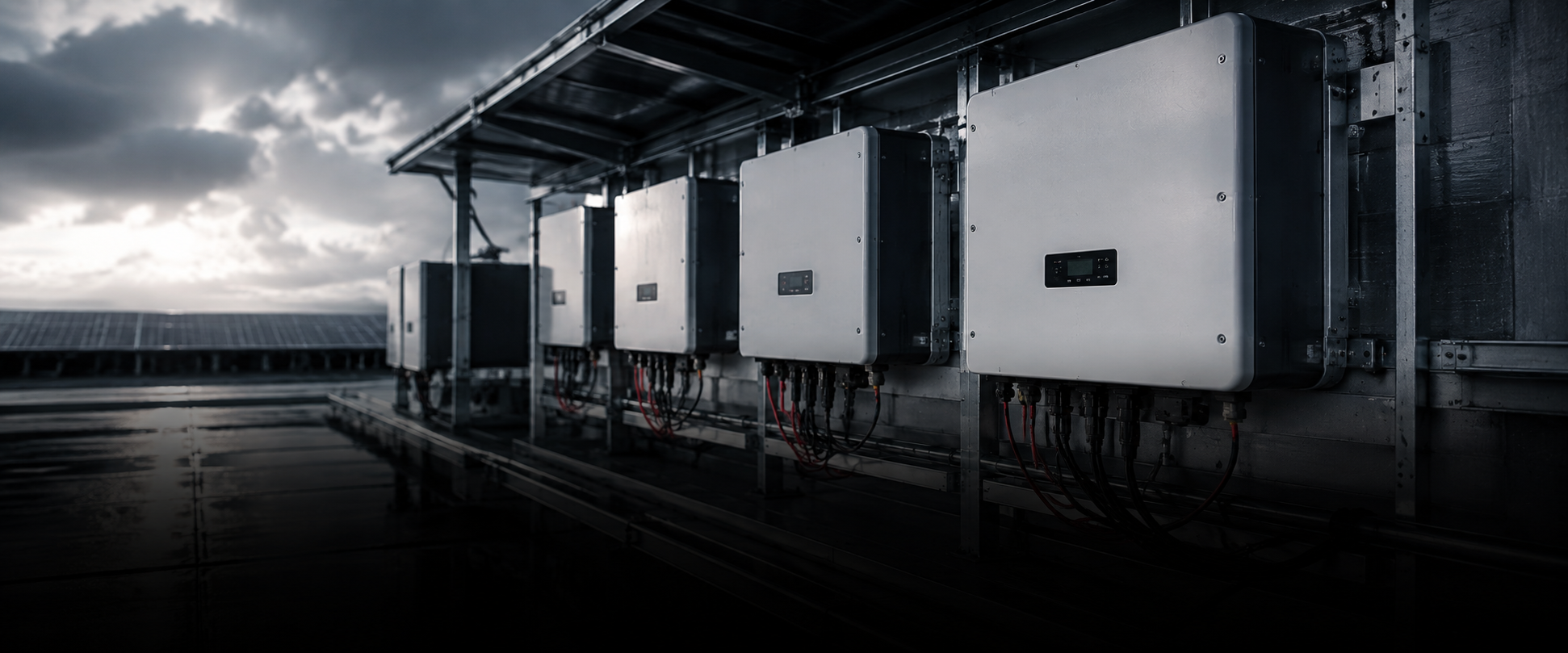
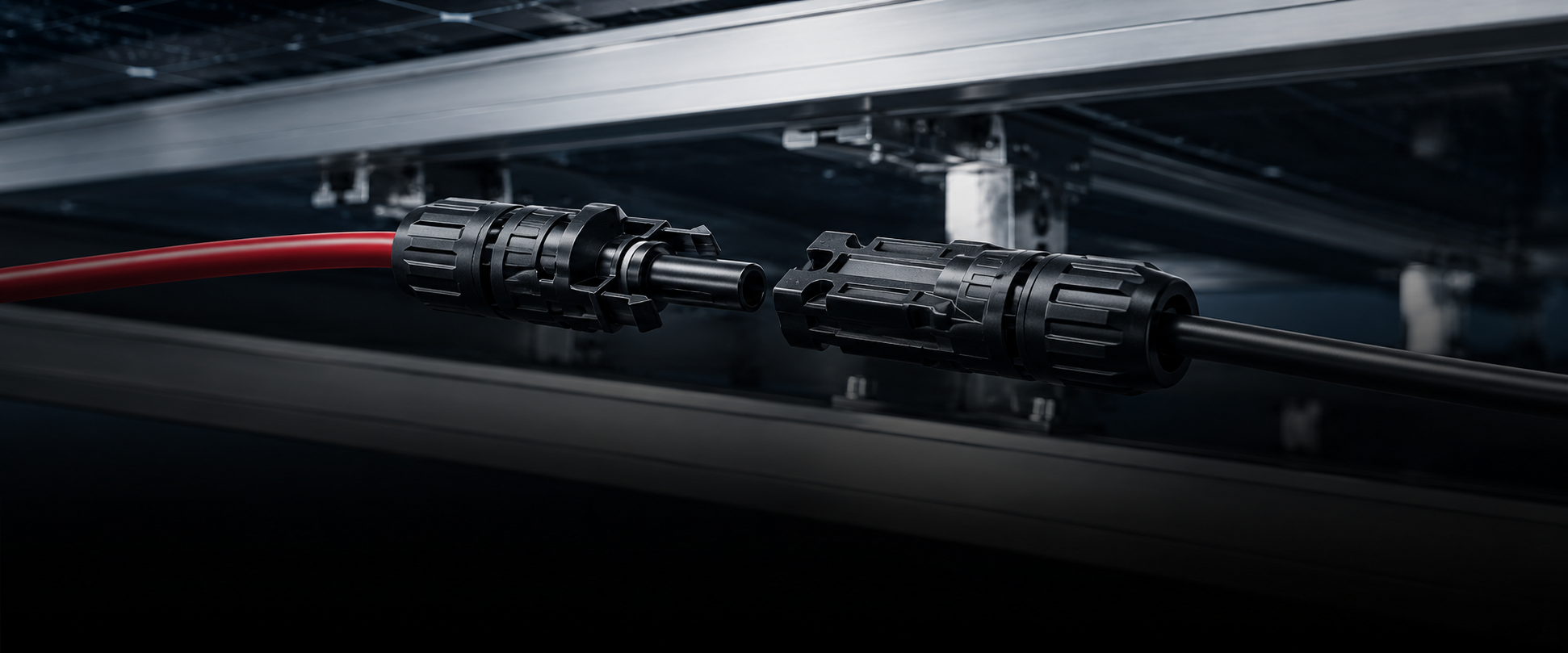
Cable solutions for connection with commonly used PV modules, inverters, connectors and balance-of-system equipment, subject to the applicable electrical and installation requirements.










Reported issues are acknowledged within 1 business day. We identify the affected product and batch and confirm any immediate action required.

Batch, production, test, delivery and available site information are reviewed to determine what happened. Initial findings are provided within 5 business days.

Based on the findings, the required action is agreed. This may include technical guidance, product replacement or other corrective measures where necessary.

The agreed action is checked before the case is closed. Relevant findings are fed back into our quality controls to help prevent recurrence.
Technical support throughout the process.


Not automatically. A PV route can pass through several installation environments, and the cable requirements may change along the way.
Standard H1Z2Z2-K is intended for permanent PV DC wiring and is available with different water-resistance and CPR combinations. Current HORNOUR configurations include Eca and Dca with AD7 or AD8, while Cca is currently available with AD7.
Wet sections therefore need the required water-resistance level, mechanically exposed or ground-level sections may need additional protection, and sections entering buildings may have different fire requirements. Direct burial should not be assumed simply because a cable is suitable for outdoor PV use. Where mechanical exposure is significant, a protected route or an appropriate armoured construction should be considered.
PV cable sizing should consider more than operating current. Route length, voltage drop, ambient temperature, cable grouping, installation method and the allowable operating temperature all affect the final selection.
A cable that is adequate in free air may operate differently when several strings are tightly grouped, installed in conduit or routed through hotter sections of a roof. The current H1Z2Z2-K range is intended to allow conductor size to be selected around current, route length and grouping rather than using one size throughout the array.
A larger conductor may also be justified where reduced voltage drop and lower long-term I²R losses outweigh the additional cable cost.
The protection level should match the actual site risk rather than using the heaviest construction everywhere.
A capsaicin-based sheath provides a chemical deterrent without adding armour. A nylon barrier adds a harder non-metallic physical layer. Steel-wire armour provides the strongest physical protection where severe rodent activity and mechanical exposure occur. These constructions are rodent-resistant rather than an absolute guarantee against damage.
Armour also changes installation requirements. Finished diameter, bending radius, support spacing, clamps, glands and equipment-entry space must be based on the final armoured construction rather than standard H1Z2Z2-K dimensions.
Not automatically. A Class 5 conductor makes H1Z2Z2-K flexible for installation, but this does not by itself mean the cable is approved for continuous repeated movement.
The standard HORNOUR H1Z2Z2-K construction is defined for permanent PV connections and fixed installation.
Where a tracker causes repeated bending, twisting or movement, the actual travel distance, bending radius, torsion, number of operating cycles, fixing points and connector strain must be evaluated separately. A cable that is flexible during installation should not be treated as a dynamic-flex cable unless its documented design and test scope covers that duty.
The choice depends on more than voltage and conductor size. NYY/NAYY use PVC insulation and sheath for conventional fixed distribution. N2XY/NA2XY use XLPE insulation where the feeder requires a higher-temperature insulation system, while N2XH/NA2XH combine XLPE insulation with a low-smoke, halogen-free sheath for routes with additional fire and smoke requirements.
Copper or aluminium, installation environment, fire requirement, operating temperature and equipment interface should therefore be considered together rather than selecting the cable by model name alone.
Two cables are equivalent only when the characteristics that affect the project also match. The same voltage rating and conductor size are not enough: conductor material and class, core arrangement, insulation, sheath, fire behaviour, installation conditions, standards and relevant dimensions all need to be compared.
For example, NYY, N2XY and N2XH can all exist in the 0.6/1 kV class but use different material systems and are not automatically interchangeable. A cross-brand equivalent should therefore be checked against the original designation, datasheet or project specification rather than the model name alone.
Aluminium is often attractive on long routes and larger feeders because it can reduce conductor cost and cable weight, but it is not normally a size-for-size replacement for copper.
Current, route length, voltage drop and installation conditions may require a larger aluminium cross-section. The resulting cable diameter, bend space and equipment-entry requirements can also change, and the termination system must be suitable for aluminium.
The comparison should therefore be made at feeder-system level rather than by conductor price per metre alone.
Conductor size has to satisfy the complete electrical duty, not only normal operating current. Route length and voltage drop can require a larger conductor even when basic current capacity is sufficient, while installation conditions affect the allowable loading of the cable.
The cable construction also defines its thermal limits. For example, the current N2XY technical data specifies a +90°C permissible conductor operating temperature and a +250°C short-circuit conductor temperature for up to 5 seconds.
Final sizing should therefore combine load, voltage-drop, installation and project short-circuit calculations with the limits of the selected cable construction.
Medium-voltage matching goes beyond voltage class and conductor size. NA2XS(F)2Y uses an aluminium conductor, XLPE insulation, semiconductive screens, a copper-wire metallic screen, longitudinal water blocking and a PE outer sheath, with versions from 6/10 kV to 18/30 kV.
Joints and terminations must match the actual insulation diameter, conductor size, screen construction and final cable dimensions. The accessory manufacturer should confirm compatibility with that exact cable construction.
Route conditions and the project’s metallic-screen earthing or bonding arrangement also need to be defined at system-design level rather than inferred from the cable designation alone.