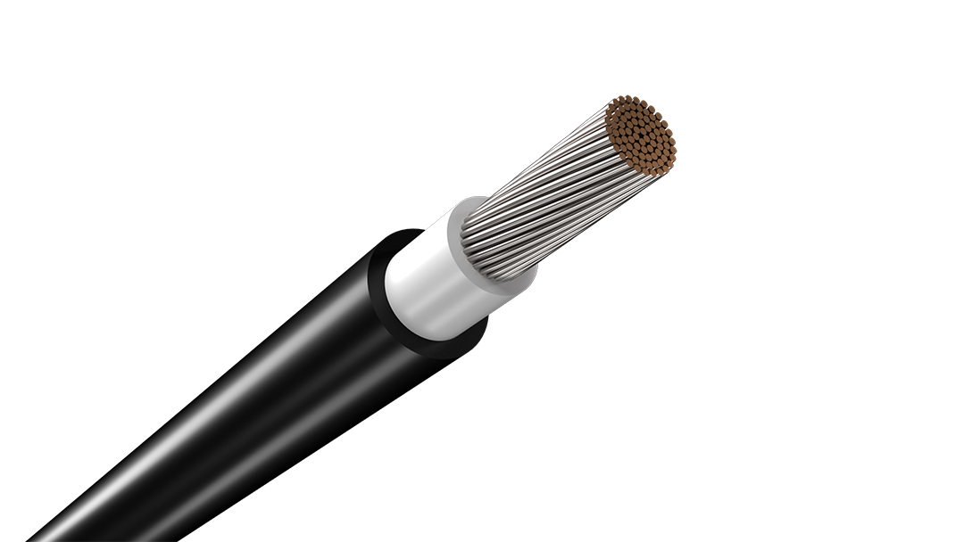
H1Z2Z2-K Nylon-Barrier Rodent-Resistant Solar Cable
H1Z2Z2-K 1.5 kV DC solar cable with a nylon barrier beneath the outer sheath for PV routes that need a non-metallic physical defence against rodent damage.


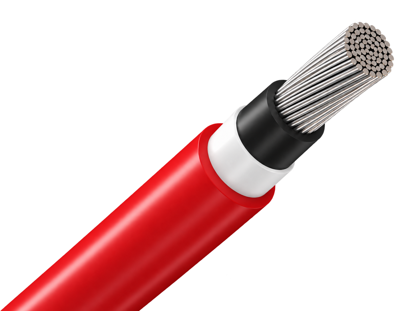
H1Z2Z2-K 1.5 kV DC solar cable with a nylon barrier beneath the outer sheath for PV routes that need a non-metallic physical defence against rodent damage.
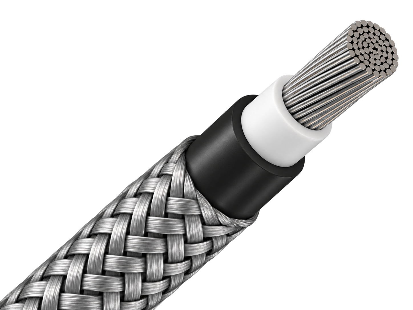
H1Z2Z2-K 1.5 kV DC solar cable with external steel-wire armour for fixed PV routes exposed to severe rodent activity or mechanical damage.
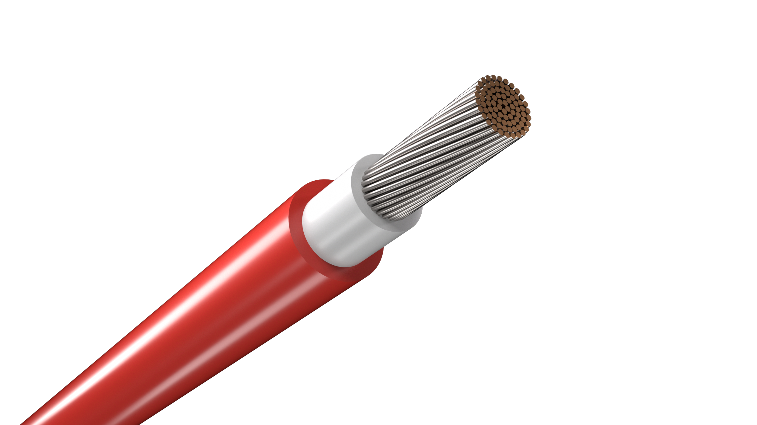
H1Z2Z2-K 1.5 kV DC solar cable with a capsaicin-based rodent-deterrent sheath for PV routes where chemical protection is preferred over added armour.
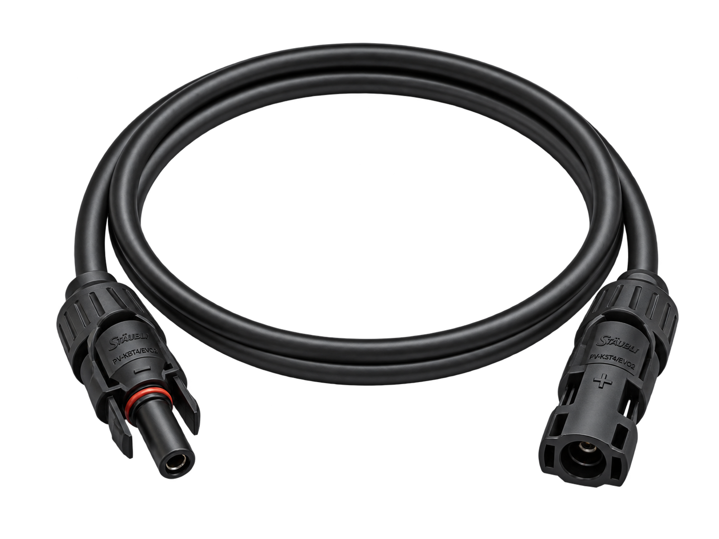
Factory-terminated PV extension cable for controlled module, string and combiner-box connections.
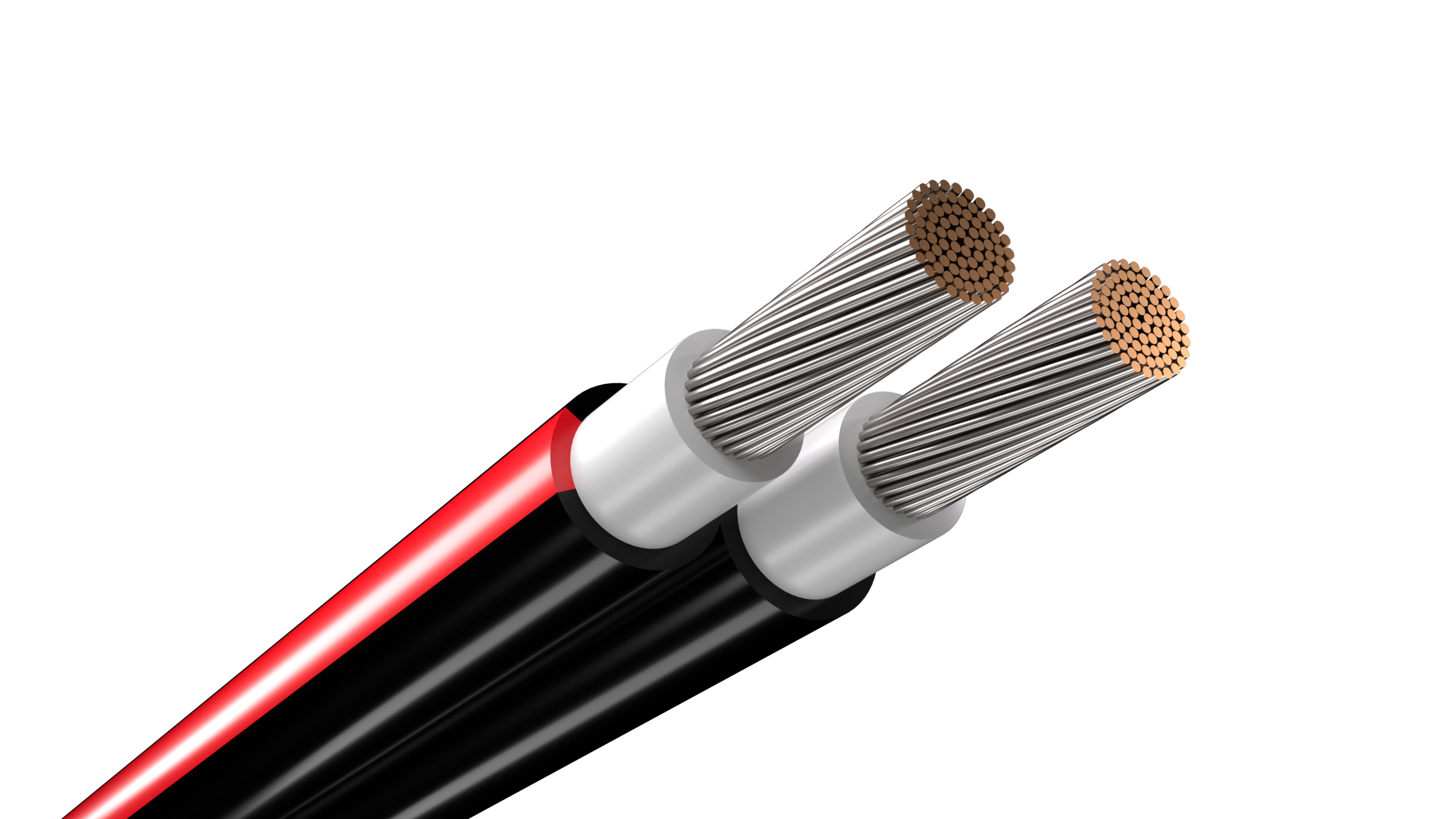
Joined twin PV cable for orderly positive and negative string routing beneath solar modules.
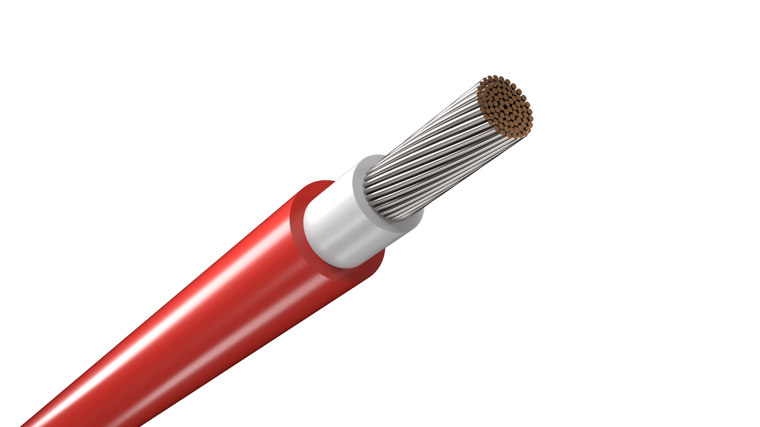
Single-core PV cable for reliable DC wiring across rooftop and ground-mounted solar arrays.
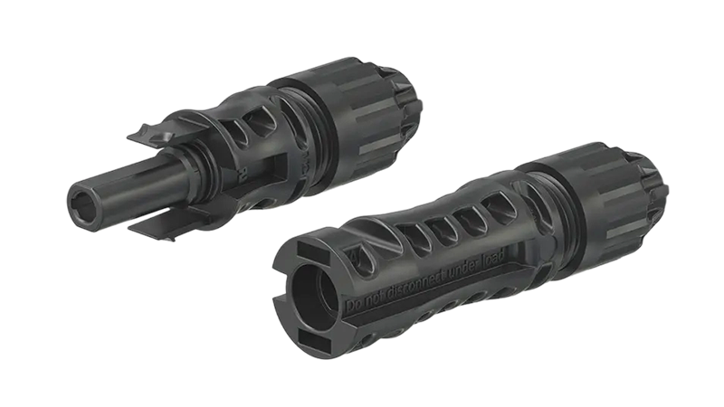
Durable DC connector for residential solar panels – UV-resistant and waterproof.
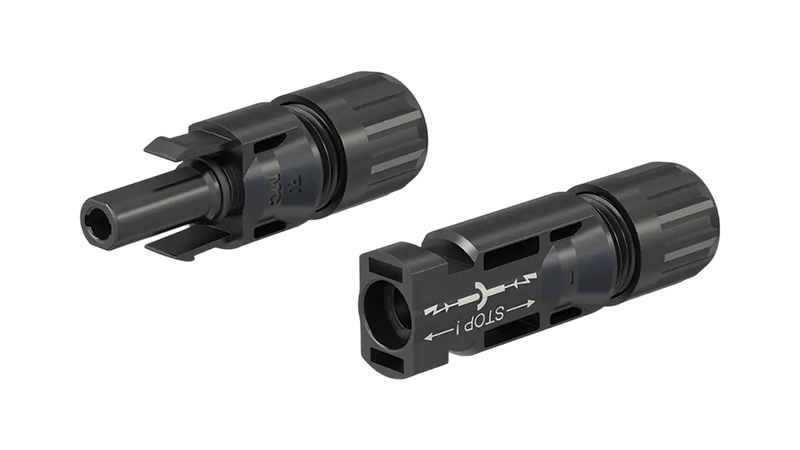
Reliable DC connection for residential photovoltaic systems, UV-resistant, waterproof, and long-lasting.

PVC-sheathed 300/500 V cable for fixed power and lighting circuits inside buildings and panels.
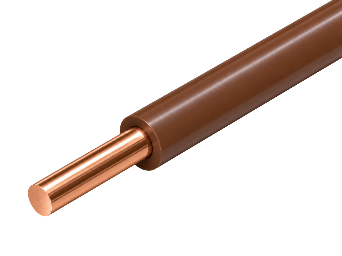
Solid 450/750 V PVC wire for stable fixed circuits in protected conduit and building installations.
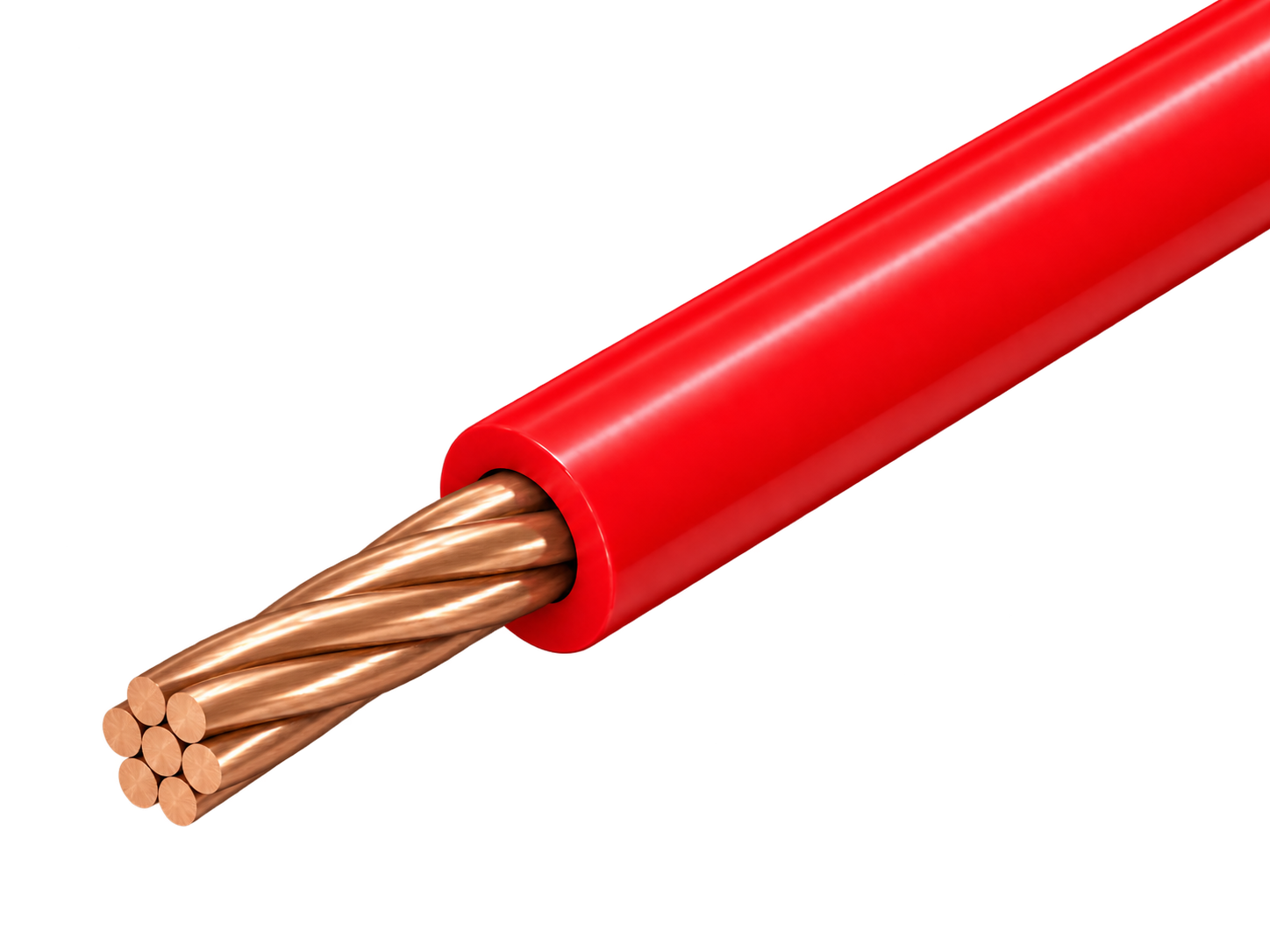
Class 2 stranded 300/500 V PVC wire for fixed equipment and panel routes needing moderate flexibility.
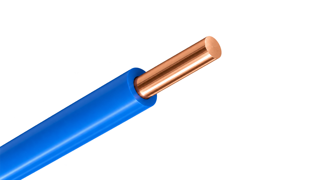
Solid 300/500 V PVC wire for simple, stable fixed connections inside protected equipment and conduit.
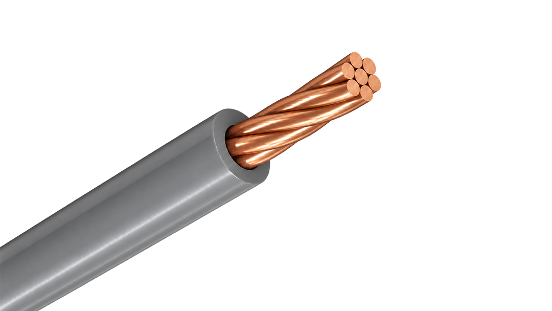
Class 2 stranded 450/750 V PVC wire for protected fixed routes requiring easier pulling and forming.
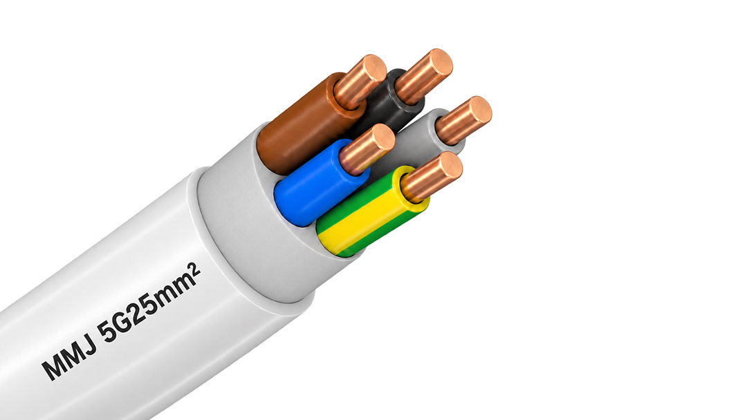
300/500 V PVC-sheathed cable for fixed surface and flush-mounted installations in Finnish building wiring.
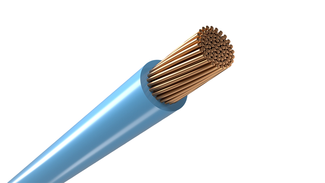
Flexible 300/500 V PVC wire for compact equipment, switchgear and control-panel connections.
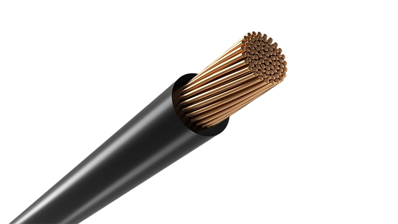
Flexible 450/750 V PVC wire for protected conduit, panel and grounding connections.
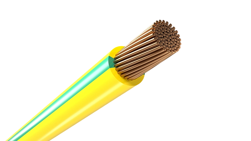
Flexible PVC insulated earthing cable for residential solar PV system grounding
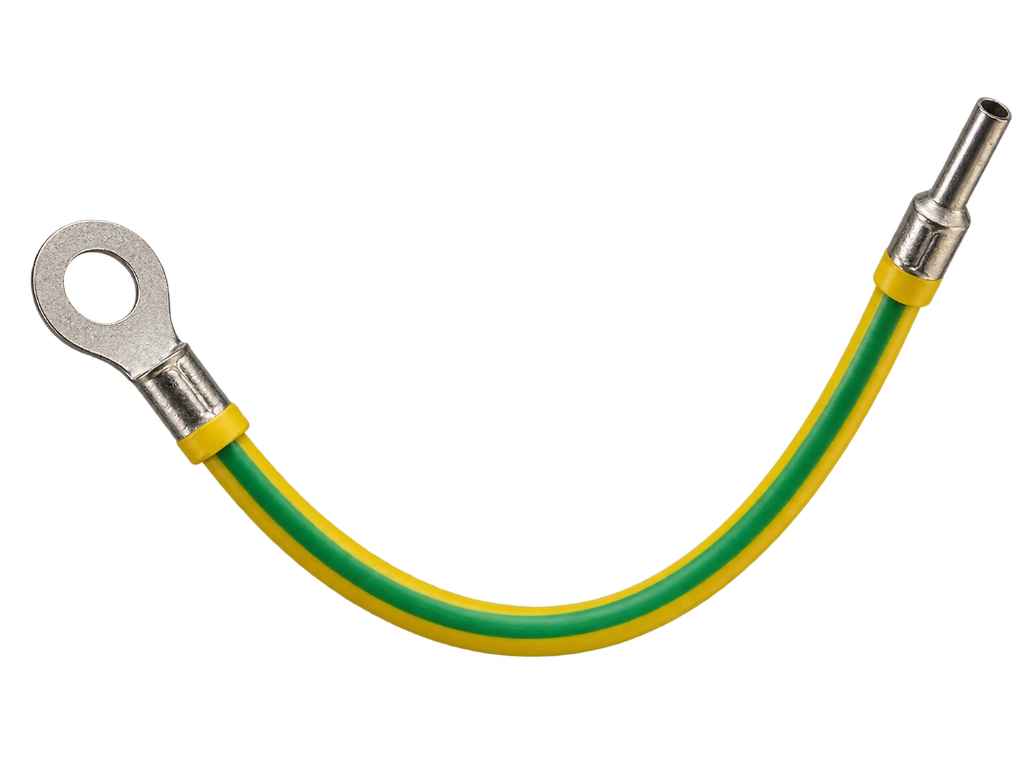
Green/yellow H07V-K grounding lead with factory-crimped ring / OT terminal for ready-to-install earthing and bonding connections.
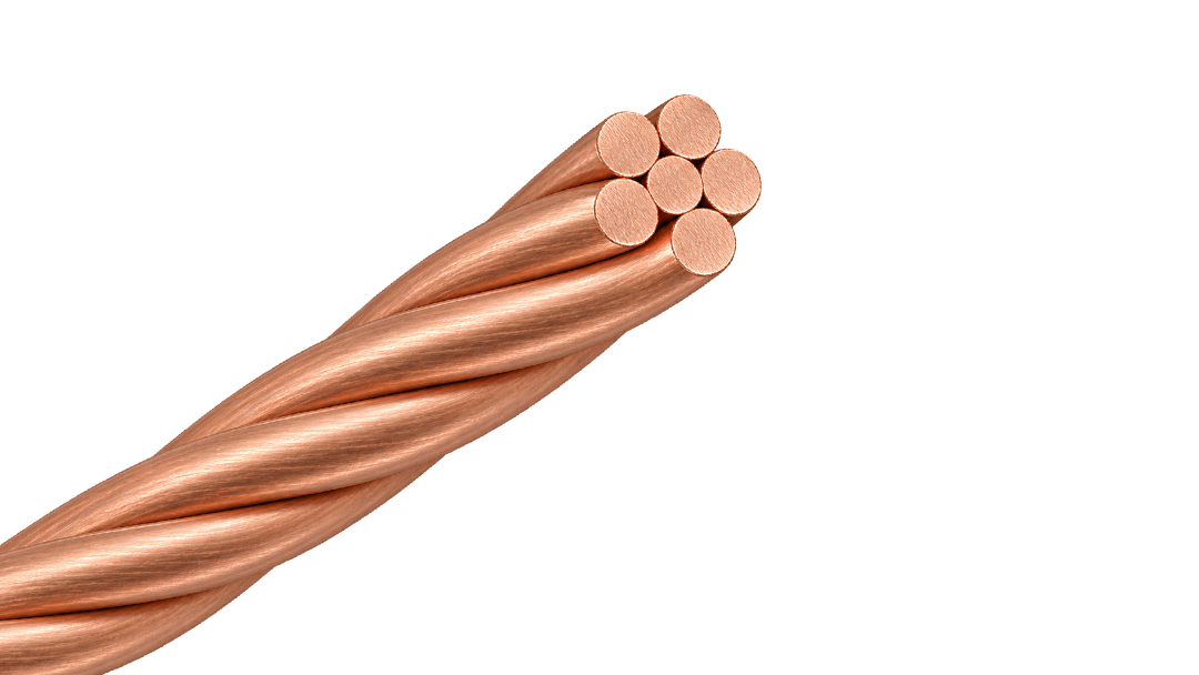
Bare 25 mm² Class 2 stranded copper conductor for earthing, grounding and equipotential bonding.
Flexible 450/750 V PVC wire for protected conduit, panel and grounding connections.
H1Z2Z2-K 1.5 kV DC solar cable with a nylon barrier beneath the outer sheath for PV routes that need a non-metallic physical defence against rodent damage.
H1Z2Z2-K 1.5 kV DC solar cable with external steel-wire armour for fixed PV routes exposed to severe rodent activity or mechanical damage.
H1Z2Z2-K 1.5 kV DC solar cable with a capsaicin-based rodent-deterrent sheath for PV routes where chemical protection is preferred over added armour.
Factory-terminated PV extension cable for controlled module, string and combiner-box connections.
Joined twin PV cable for orderly positive and negative string routing beneath solar modules.
Single-core PV cable for reliable DC wiring across rooftop and ground-mounted solar arrays.
Flexible PVC insulated earthing cable for residential solar PV system grounding
Green/yellow H07V-K grounding lead with factory-crimped ring / OT terminal for ready-to-install earthing and bonding connections.
Bare 25 mm² Class 2 stranded copper conductor for earthing, grounding and equipotential bonding.
Flexible 450/750 V PVC wire for protected conduit, panel and grounding connections.
PVC-sheathed 300/500 V cable for fixed power and lighting circuits inside buildings and panels.
Solid 450/750 V PVC wire for stable fixed circuits in protected conduit and building installations.
Class 2 stranded 300/500 V PVC wire for fixed equipment and panel routes needing moderate flexibility.
Solid 300/500 V PVC wire for simple, stable fixed connections inside protected equipment and conduit.
Class 2 stranded 450/750 V PVC wire for protected fixed routes requiring easier pulling and forming.
300/500 V PVC-sheathed cable for fixed surface and flush-mounted installations in Finnish building wiring.
Flexible 300/500 V PVC wire for compact equipment, switchgear and control-panel connections.
Flexible 450/750 V PVC wire for protected conduit, panel and grounding connections.
2Y-1220-kV.png)
Aluminium XLPE medium-voltage cable with longitudinal water blocking for fixed distribution networks.
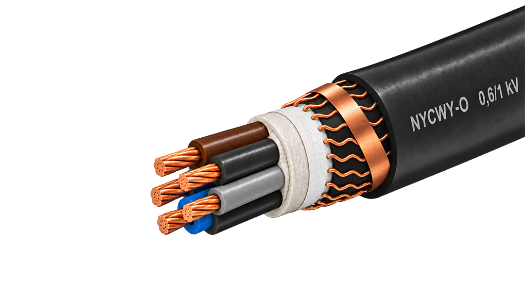
0.6/1 kV copper cable with a wave-laid concentric conductor for fixed distribution and service routes.
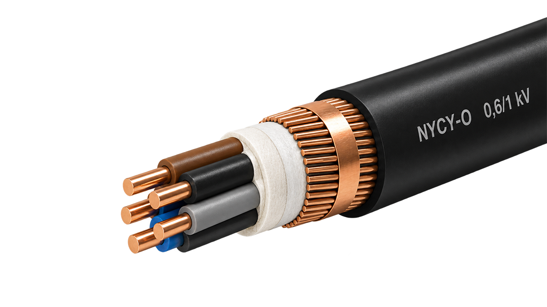
0.6/1 kV copper power cable with a concentric copper layer for service and distribution circuits.
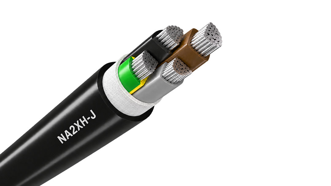
Aluminium halogen-free 0.6/1 kV cable for fire-conscious fixed distribution and long feeders.
XLPE Insulated and PVC Sheathed Heavy-Duty Power Cable for Commercial & Industrial Applications
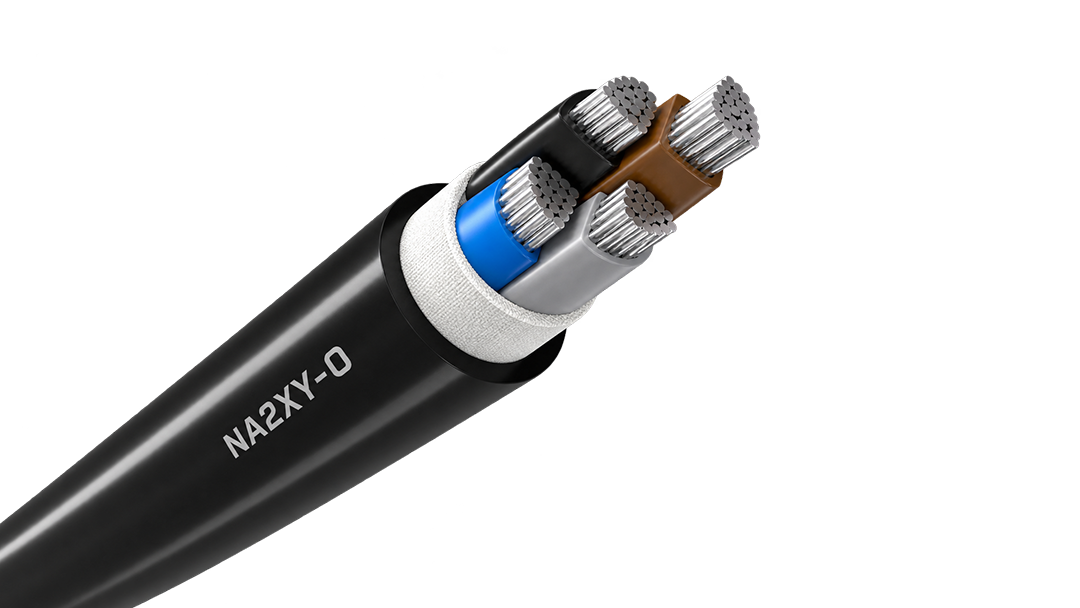
Aluminium XLPE 0.6/1 kV cable for economical high-current fixed distribution and long routes.
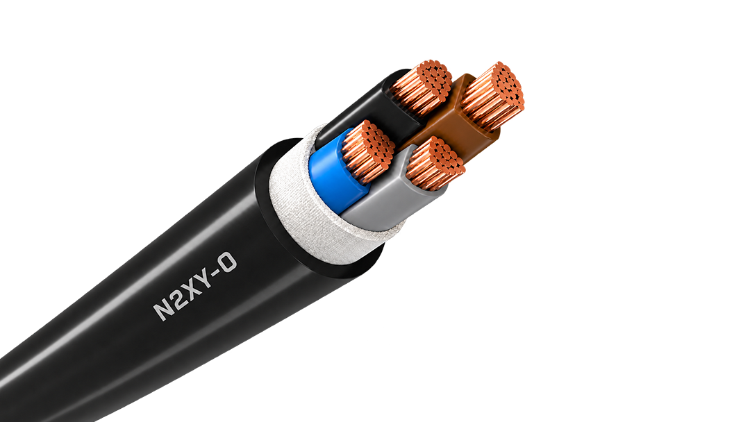
Copper XLPE 0.6/1 kV cable for demanding fixed feeders, outdoor routes and power distribution.
Aluminium 0.6/1 kV PVC cable for cost-conscious fixed distribution and long feeder routes.
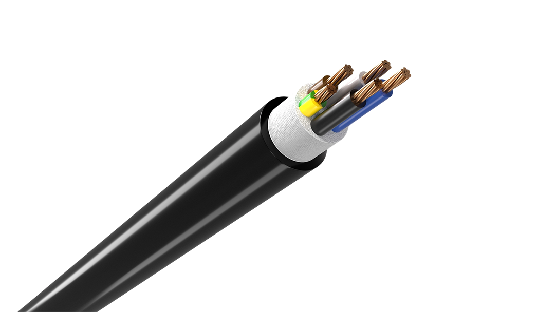
Robust 0.6/1 kV copper cable for economical fixed power distribution indoors, outdoors and underground.
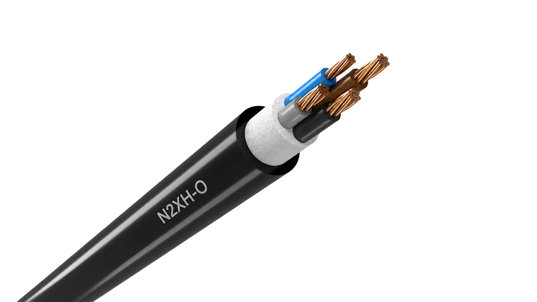
Low-smoke halogen-free 0.6/1 kV cable for fixed distribution in occupied and critical buildings.

hot search


NA2XS(F)2Y combines aluminium, XLPE insulation, a copper-wire screen and longitudinal water blocking for MV feeders.
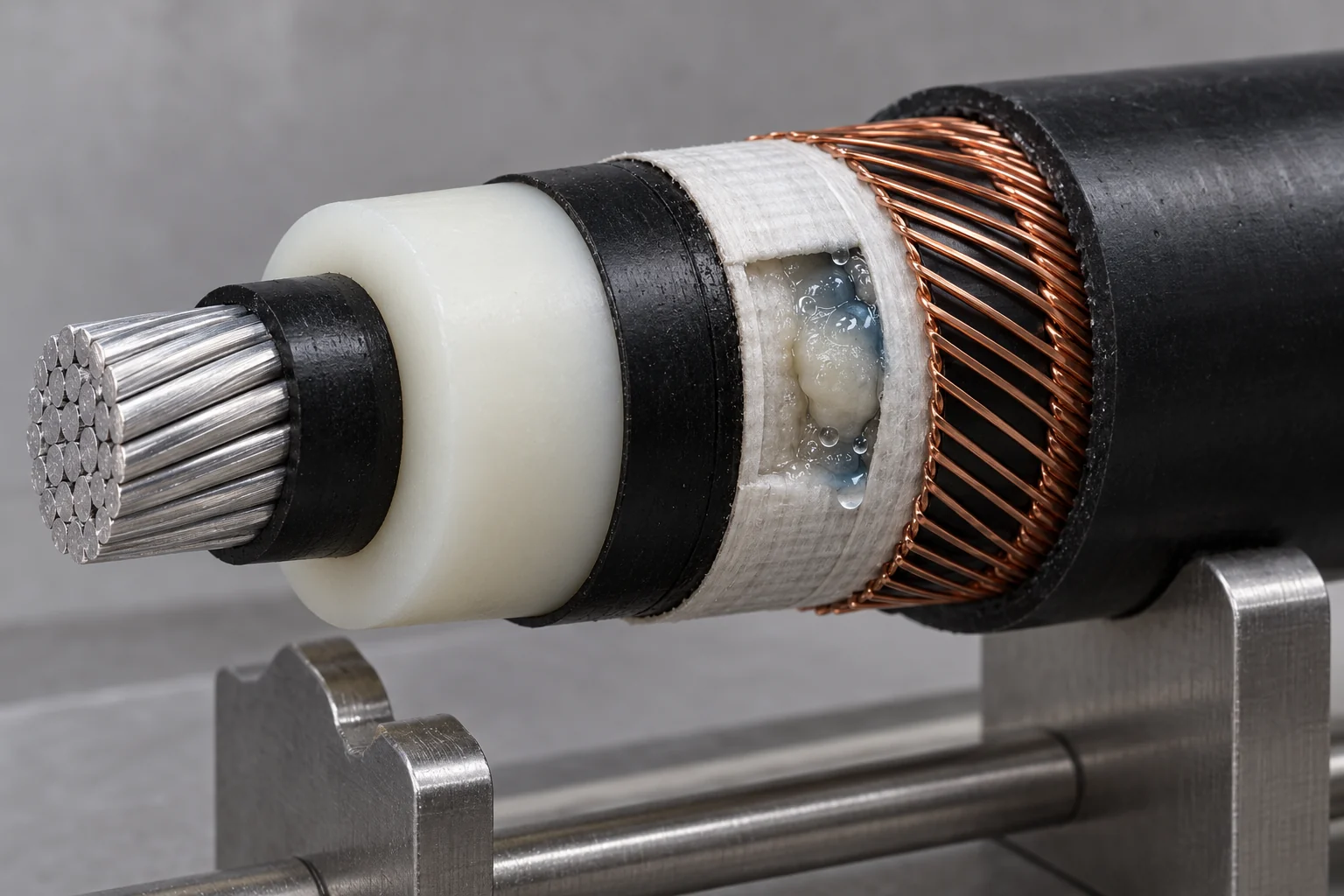
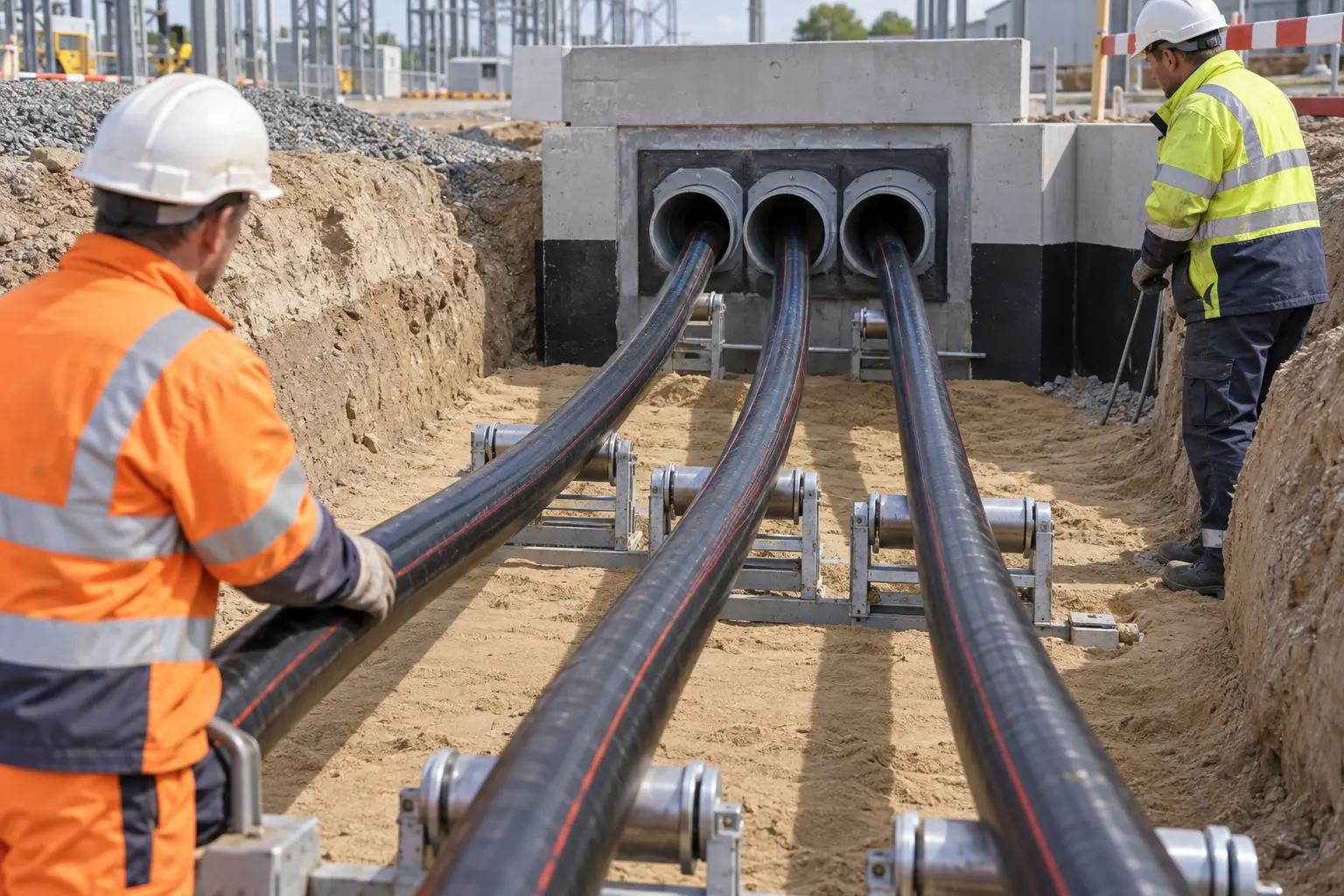
Underground medium-voltage routes are expensive to access if water enters through local sheath damage and migrates along the cable. NA2XS(F)2Y adds a water-swellable layer around the screened XLPE construction to restrict longitudinal moisture movement. This is particularly valuable on long collector and substation feeders where containing water at the damaged section can reduce the extent of future repair work.
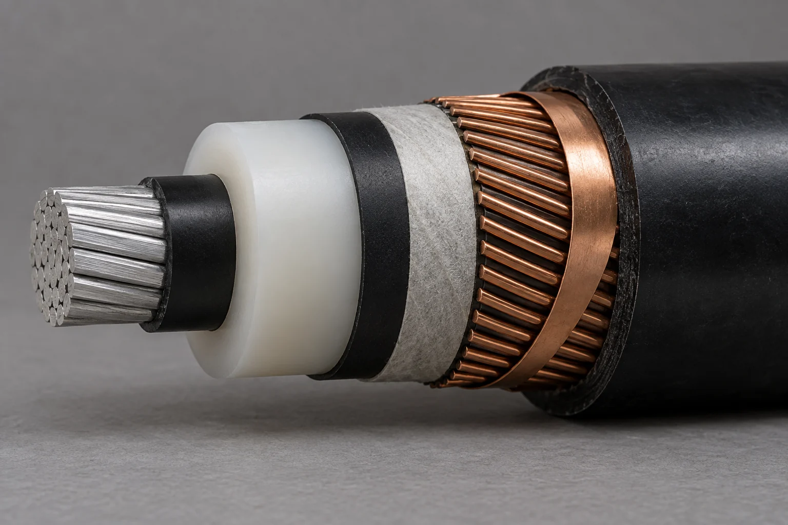
The cable combines a Class 2 aluminium conductor, XLPE insulation, copper-wire metallic screen and PE outer sheath across 6/10 kV to 18/30 kV constructions. That makes it a strong fit for utility PV collector systems, substations and underground distribution networks where long distances make aluminium conductor economy important and the cable still needs a complete screened MV insulation system.
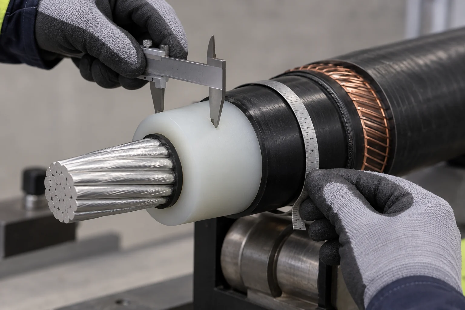
Medium-voltage joints and terminations are selected around the cable’s insulation diameter, screen construction and conductor size. NA2XS(F)2Y provides those elements in a defined screened cable design, allowing the approved accessory system to be matched before installation. This supports repeatable jointing and termination work across long MV projects with many identical connection points.
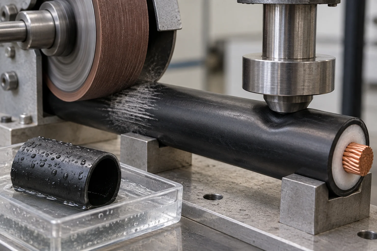
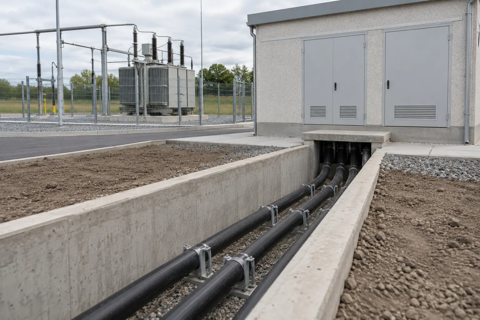
The polyethylene outer sheath is well suited to fixed external, ducted and underground medium-voltage routes where moisture resistance and mechanical durability are important. For sections entering buildings or other locations with defined fire-performance requirements, the sheath and installation system should be selected against the project’s fire specification rather than assuming an external PE construction provides the same fire behaviour as an indoor LSZH cable.
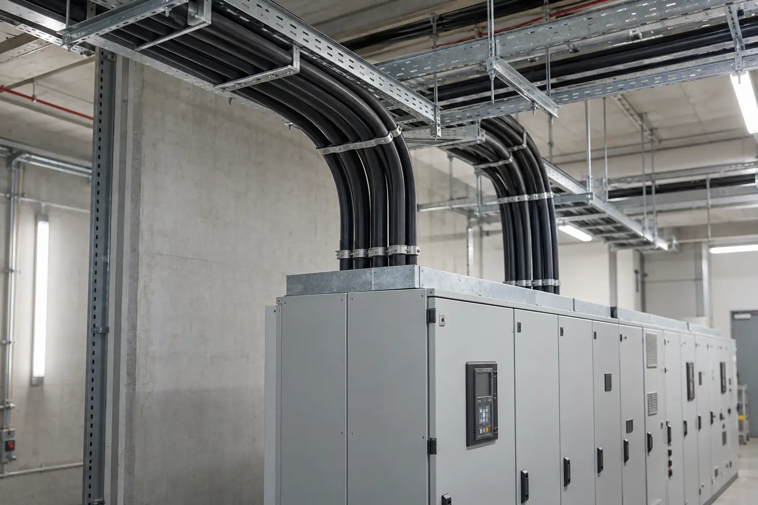
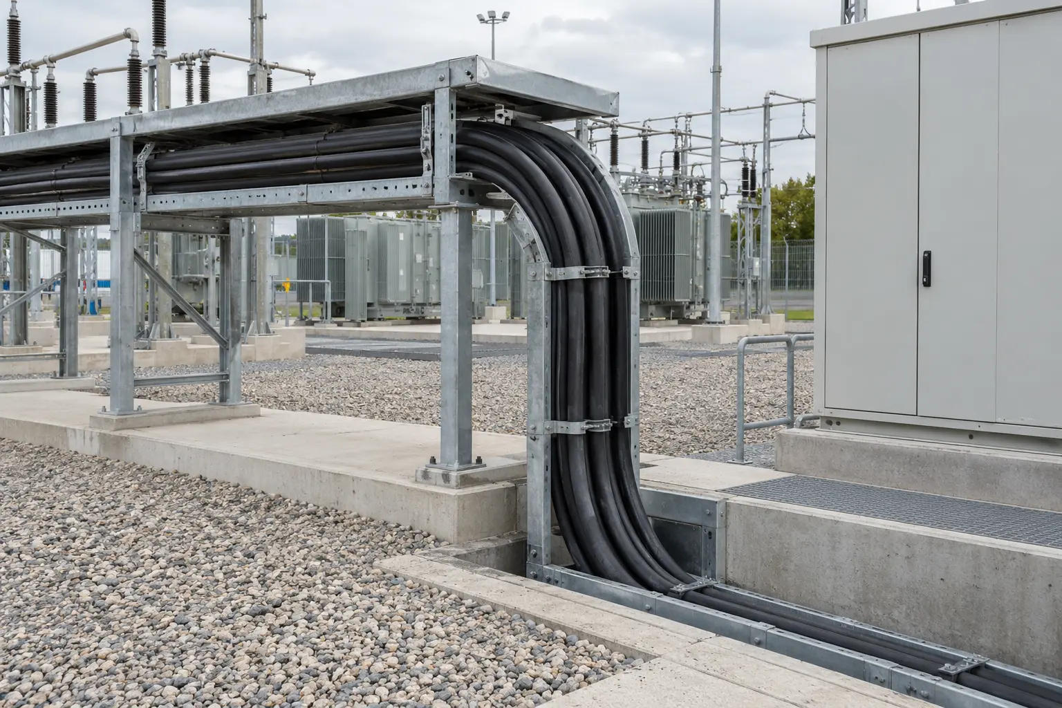
Designed for PV collector networks, Substation feeders, Utility infrastructure and Underground MV routes.
| Configuration conductor / screen mm² | Conductor OD mm | Semi-con layer inner / outer mm | Insulation mm | Wire screen mm² | Sheath mm | Overall diameter mm | Approx. weight kg/km |
|---|---|---|---|---|---|---|---|
| 1 × 50 / 16 | 8.20 | 0.50 / 0.40 | 3.40 | 16 | 1.80 | 23 | 550 |
| 1 × 70 / 16 | 9.70 | 0.50 / 0.40 | 3.40 | 16 | 1.80 | 24 | 650 |
| 1 × 95 / 16 | 11.4 | 0.50 / 0.40 | 3.40 | 16 | 1.80 | 26 | 750 |
| 1 × 120 / 16 | 12.65 | 0.50 / 0.40 | 3.40 | 16 | 1.80 | 27 | 850 |
| 1 × 150 / 25 | 14.4 | 0.50 / 0.40 | 3.40 | 25 | 1.90 | 29 | 1100 |
| 1 × 185 / 25 | 15.75 | 0.50 / 0.40 | 3.40 | 25 | 1.90 | 31 | 1200 |
| 1 × 240 / 25 | 18.2 | 0.50 / 0.40 | 3.40 | 25 | 2.00 | 33 | 1400 |
| 1 × 300 / 25 | 20.5 | 0.50 / 0.40 | 3.40 | 25 | 2.10 | 36 | 1600 |
| 1 × 400 / 35 | 23.0 | 0.50 / 0.40 | 3.40 | 35 | 2.20 | 39 | 2000 |
| 1 × 500 / 35 | 26.0 | 0.50 / 0.40 | 3.40 | 35 | 2.30 | 42 | 2500 |
| 1 × 630 / 35 | 30.2 | 0.50 / 0.40 | 3.40 | 35 | 2.40 | 46 | 3000 |
Dimensions are nominal. 35 mm² is not included in this table; accessory selection should use the exact cable dimensions for the chosen size.
| Configuration conductor / screen mm² | Conductor OD mm | Semi-con layer inner / outer mm | Insulation mm | Wire screen mm² | Tape screen mm | Sheath mm | Overall diameter mm | Approx. weight kg/km |
|---|---|---|---|---|---|---|---|---|
| 1 × 50 / 16 | 8.1 | 0.7 / 0.7 | 5.5 | 16 | 0.1 | 1.8 | 27 | 700 |
| 1 × 70 / 16 | 9.7 | 0.7 / 0.7 | 5.5 | 16 | 0.1 | 1.9 | 29 | 800 |
| 1 × 95 / 16 | 11.4 | 0.7 / 0.7 | 5.5 | 16 | 0.1 | 1.9 | 31 | 900 |
| 1 × 120 / 16 | 12.7 | 0.7 / 0.7 | 5.5 | 16 | 0.1 | 2.0 | 32 | 1000 |
| 1 × 150 / 25 | 14.5 | 0.7 / 0.7 | 5.5 | 25 | 0.1 | 2.0 | 34 | 1200 |
| 1 × 185 / 25 | 15.9 | 0.7 / 0.7 | 5.5 | 25 | 0.1 | 2.1 | 36 | 1400 |
| 1 × 240 / 25 | 18.6 | 0.7 / 0.7 | 5.5 | 25 | 0.1 | 2.1 | 39 | 1650 |
| 1 × 300 / 25 | 20.7 | 0.7 / 0.7 | 5.5 | 25 | 0.1 | 2.2 | 41 | 1950 |
| 1 × 400 / 35 | 23.5 | 0.7 / 0.7 | 5.5 | 35 | 0.1 | 2.3 | 44 | 2300 |
| 1 × 500 / 35 | 26.5 | 0.7 / 0.7 | 5.5 | 35 | 0.1 | 2.4 | 48 | 2800 |
| 1 × 630 / 35 | 30.2 | 0.7 / 0.7 | 5.5 | 35 | 0.1 | 2.5 | 52 | 3350 |
The listed dimensional range starts at 50 mm²; 35 mm² is not included in this table.
| Configuration conductor / screen mm² | Conductor OD mm | Semi-con layer inner / outer mm | Insulation mm | Wire screen mm² | Tape screen | Sheath mm | Overall diameter mm | Approx. weight kg/km |
|---|---|---|---|---|---|---|---|---|
| 1 × 50 / 16 | 8.1 | 0.7 / 0.7 | 8.0 | 16 | 0.1 × 10 | 2.0 | 33 | 1000 |
| 1 × 70 / 16 | 9.7 | 0.7 / 0.7 | 8.0 | 16 | 0.1 × 10 | 2.0 | 35 | 1100 |
| 1 × 95 / 16 | 11.4 | 0.7 / 0.7 | 8.0 | 16 | 0.1 × 10 | 2.1 | 37 | 1300 |
| 1 × 120 / 16 | 12.7 | 0.7 / 0.7 | 8.0 | 16 | 0.1 × 10 | 2.1 | 38 | 1400 |
| 1 × 150 / 25 | 14.5 | 0.7 / 0.7 | 8.0 | 25 | 0.1 × 10 | 2.2 | 40 | 1600 |
| 1 × 185 / 25 | 15.9 | 0.7 / 0.7 | 8.0 | 25 | 0.1 × 10 | 2.2 | 42 | 1800 |
| 1 × 240 / 25 | 18.6 | 0.7 / 0.7 | 8.0 | 25 | 0.1 × 10 | 2.3 | 44 | 2000 |
| 1 × 300 / 25 | 20.7 | 0.7 / 0.7 | 8.0 | 25 | 0.1 × 10 | 2.4 | 47 | 2250 |
| 1 × 400 / 35 | 23.5 | 0.7 / 0.7 | 8.0 | 35 | 0.1 × 10 | 2.5 | 50 | 2750 |
| 1 × 500 / 35 | 26.5 | 0.7 / 0.7 | 8.0 | 35 | 0.1 × 10 | 2.6 | 53 | 3250 |
| 1 × 630 / 35 | 30.2 | 0.7 / 0.7 | 8.0 | 35 | 0.1 × 10 | 2.7 | 57 | 3750 |
Dimensions are nominal and vary by conductor size.
Download TDS
Yes. Once the voltage class and conductor size are fixed, the relevant insulation diameter, screen construction and cable dimensions can be confirmed from the final cable data. The joint or termination manufacturer should then verify that its accessory is suitable for that exact cable construction.
Yes. Send the exact cable designation and, where possible, the existing datasheet or project specification. We compare conductor material, construction, voltage rating, standards and the requirements that affect the installation before confirming whether an equivalent can be offered.
Send the exact requirement. The website does not represent every possible production combination. We will check whether the construction can be supplied and whether the required standards or certification scope also cover that version before it is quoted.
Requested drum lengths can be reviewed with the cable schedule. What is practical depends on cable dimensions and weight, total quantity, drum capacity and transport or site-handling limits, so the required lengths should be included with the enquiry.