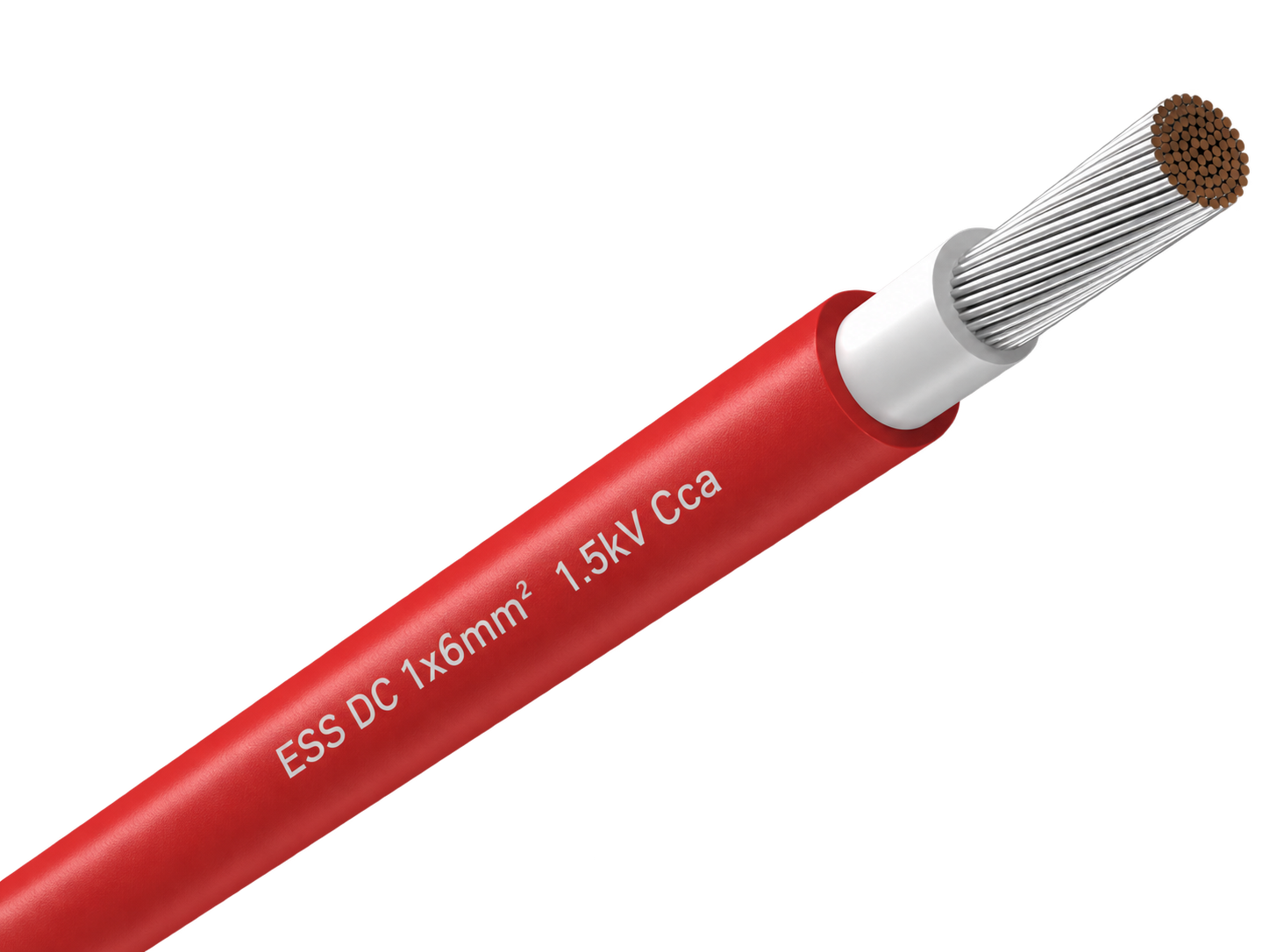
H1Z2Z2-K Nylon-Barrier Rodent-Resistant Solar Cable
H1Z2Z2-K 1.5 kV DC solar cable with a nylon barrier beneath the outer sheath for PV routes that need a non-metallic physical defence against rodent damage.

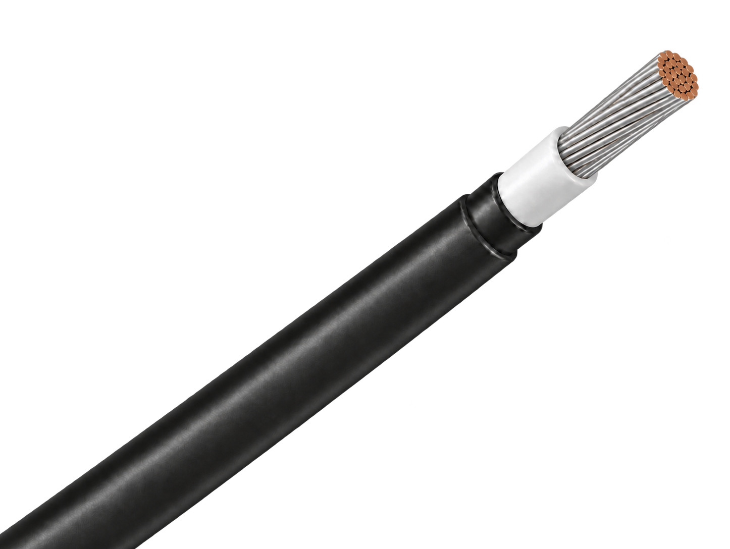
H1Z2Z2-K 1.5 kV DC solar cable with a nylon barrier beneath the outer sheath for PV routes that need a non-metallic physical defence against rodent damage.
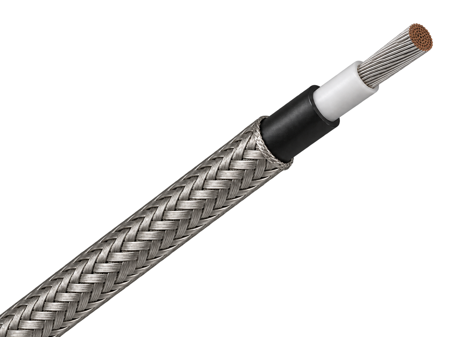
H1Z2Z2-K 1.5 kV DC solar cable with external steel-wire armour for fixed PV routes exposed to severe rodent activity or mechanical damage.
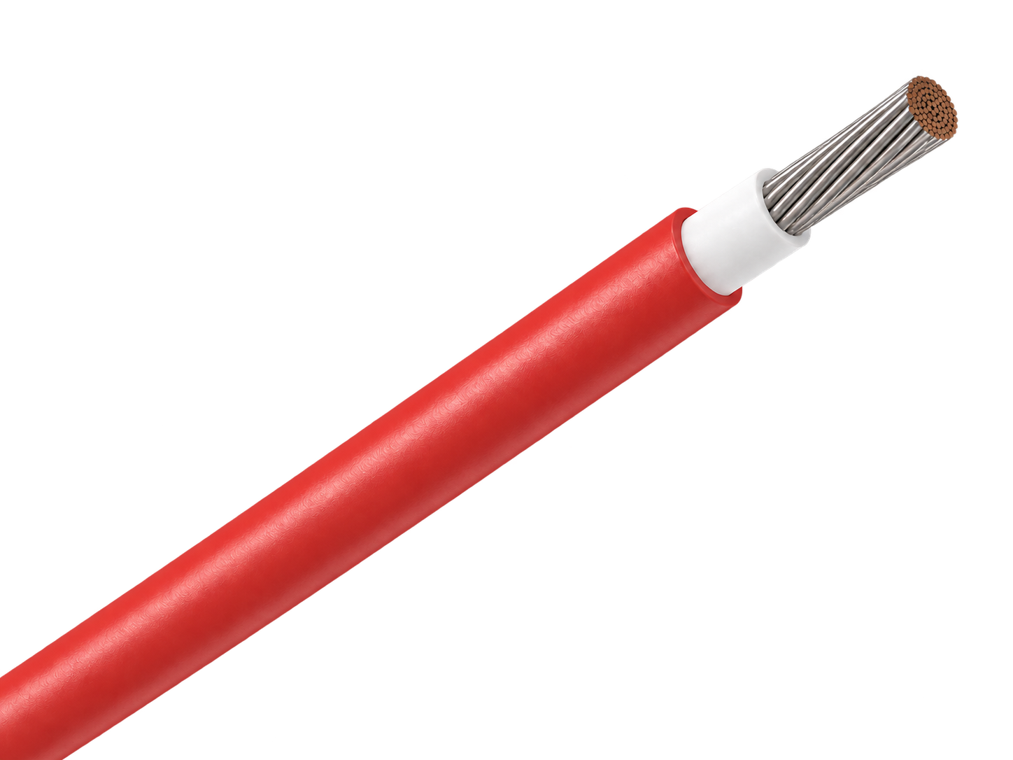
H1Z2Z2-K 1.5 kV DC solar cable with a capsaicin-based rodent-deterrent sheath for PV routes where chemical protection is preferred over added armour.
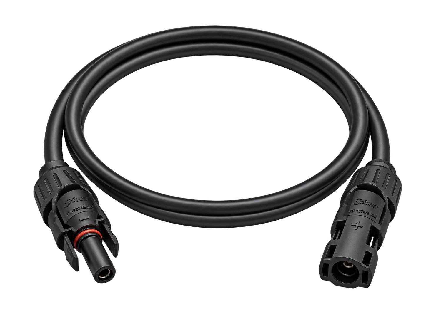
Factory-terminated PV extension cable for controlled module, string and combiner-box connections.
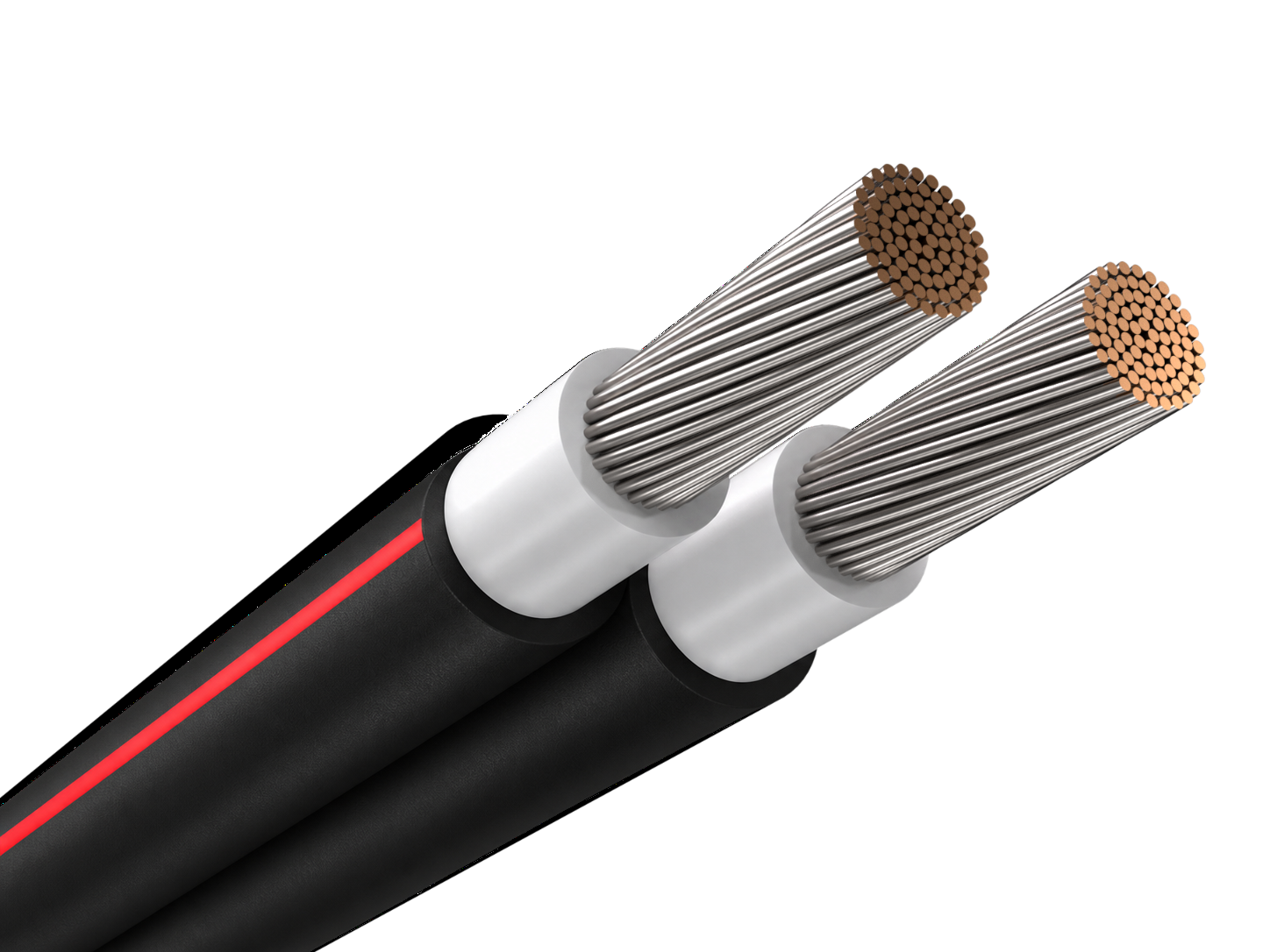
Joined twin PV cable for orderly positive and negative string routing beneath solar modules.
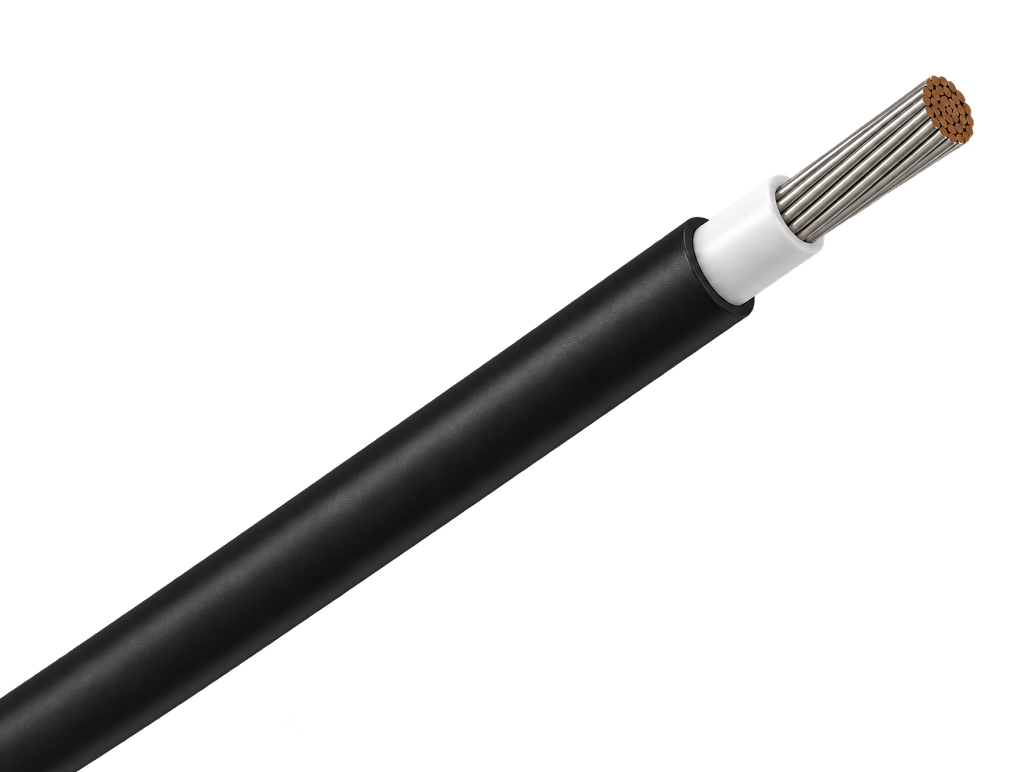
Single-core PV cable for reliable DC wiring across rooftop and ground-mounted solar arrays.
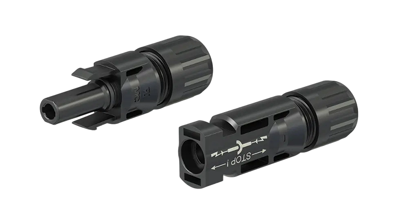
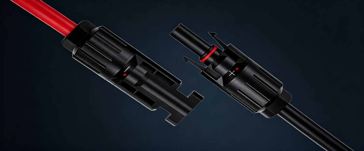
Original 4 mm DC PV connector for field-assembled module, string and extension-cable connections.
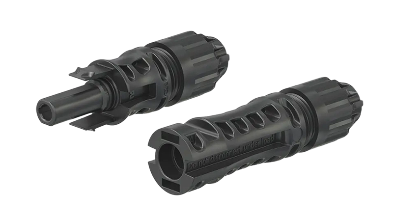
1500 V DC Original Stäubli PV connector for high-current string, extension and equipment connections.
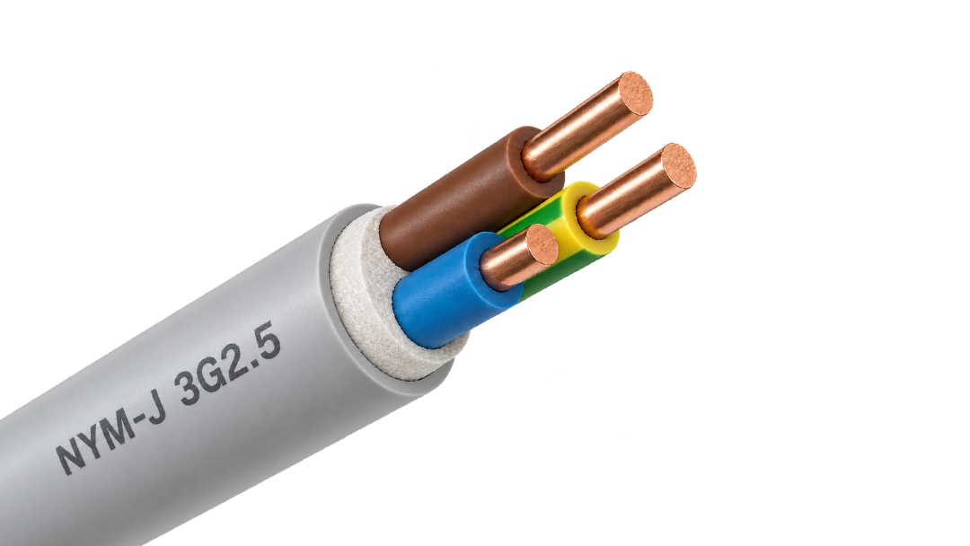
PVC-sheathed 300/500 V cable for fixed power and lighting circuits inside buildings and panels.
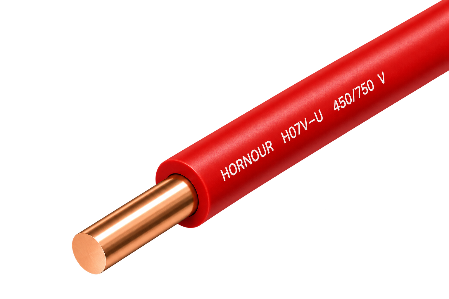
Solid 450/750 V PVC wire for stable fixed circuits in protected conduit and building installations.
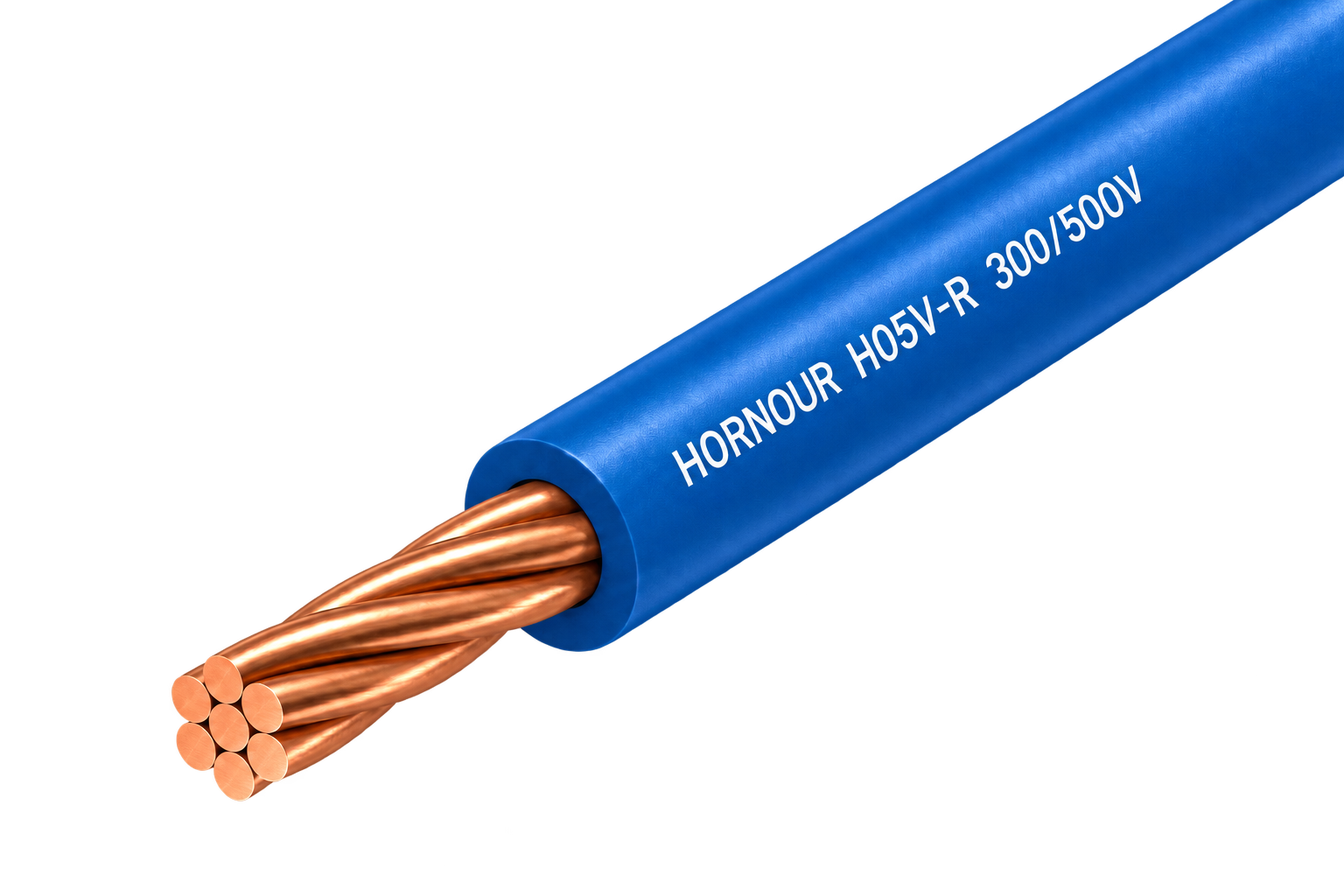
Class 2 stranded 300/500 V PVC wire for fixed equipment and panel routes needing moderate flexibility.
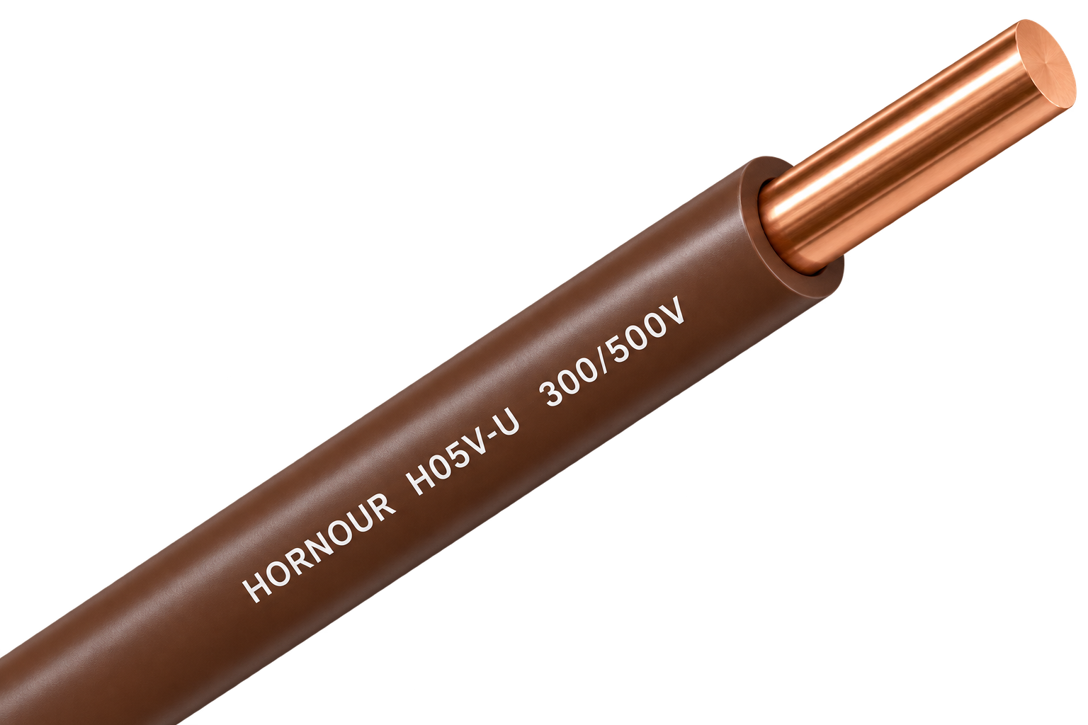
Solid 300/500 V PVC wire for simple, stable fixed connections inside protected equipment and conduit.
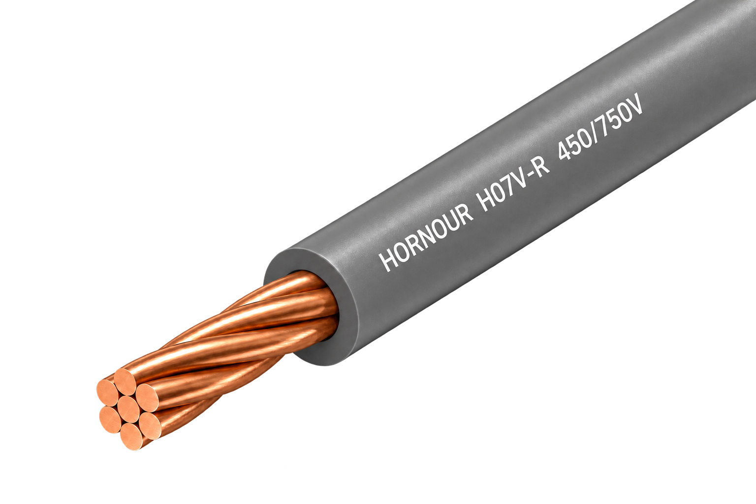
Class 2 stranded 450/750 V PVC wire for protected fixed routes requiring easier pulling and forming.
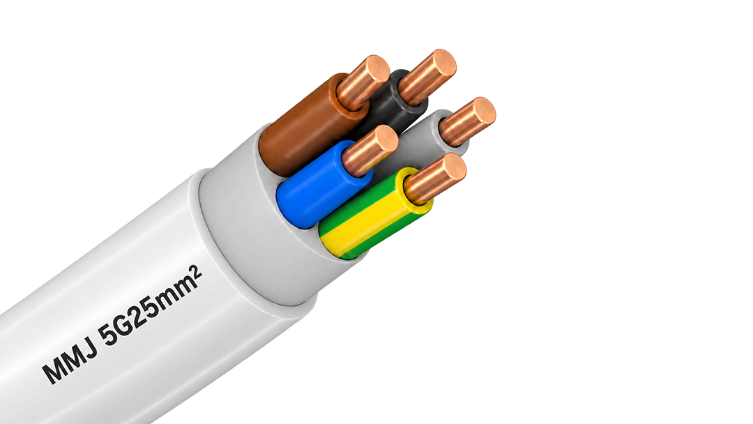
300/500 V PVC-sheathed cable for fixed surface and flush-mounted installations in Finnish building wiring.
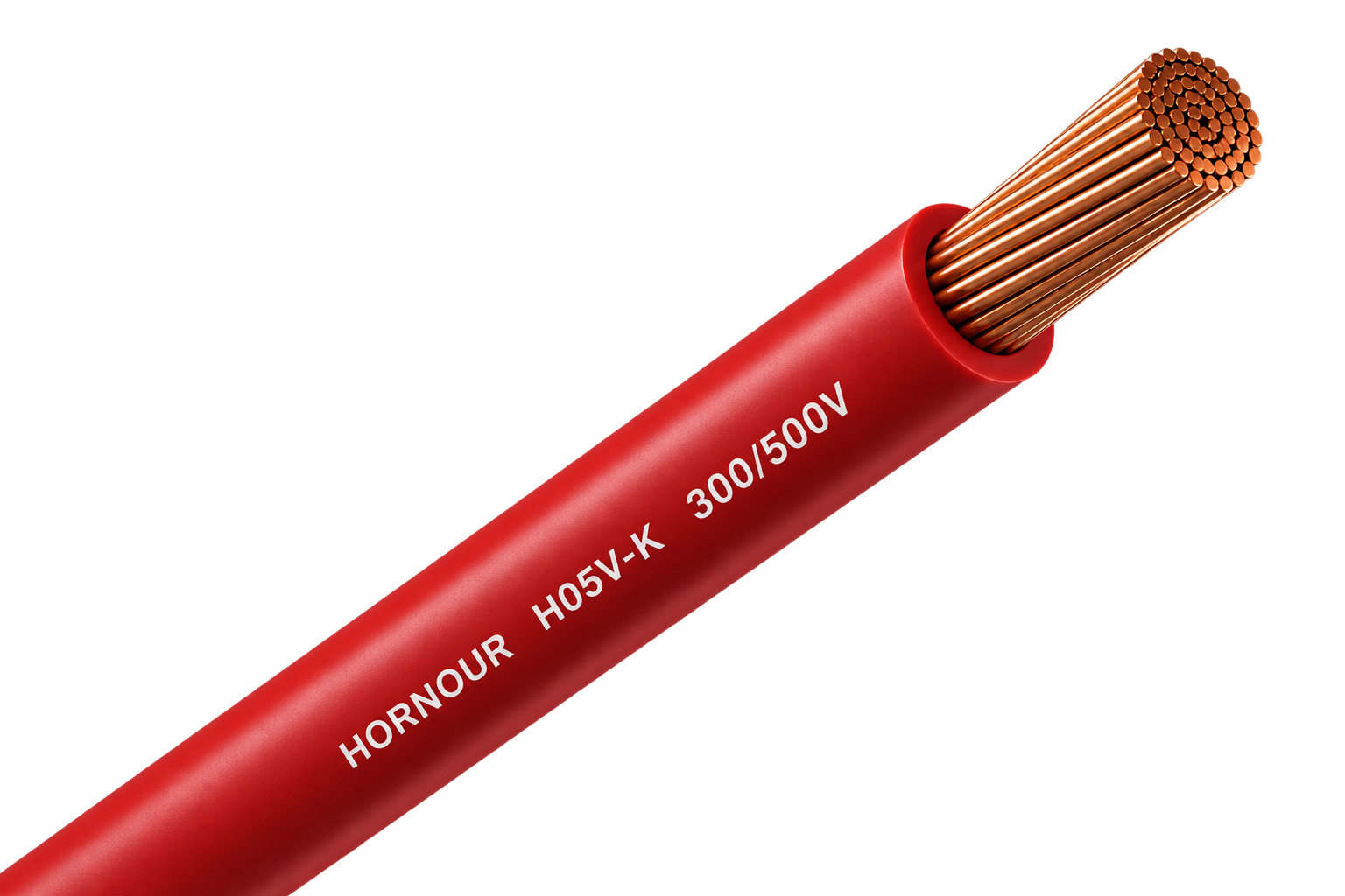
Flexible 300/500 V PVC wire for compact equipment, switchgear and control-panel connections.
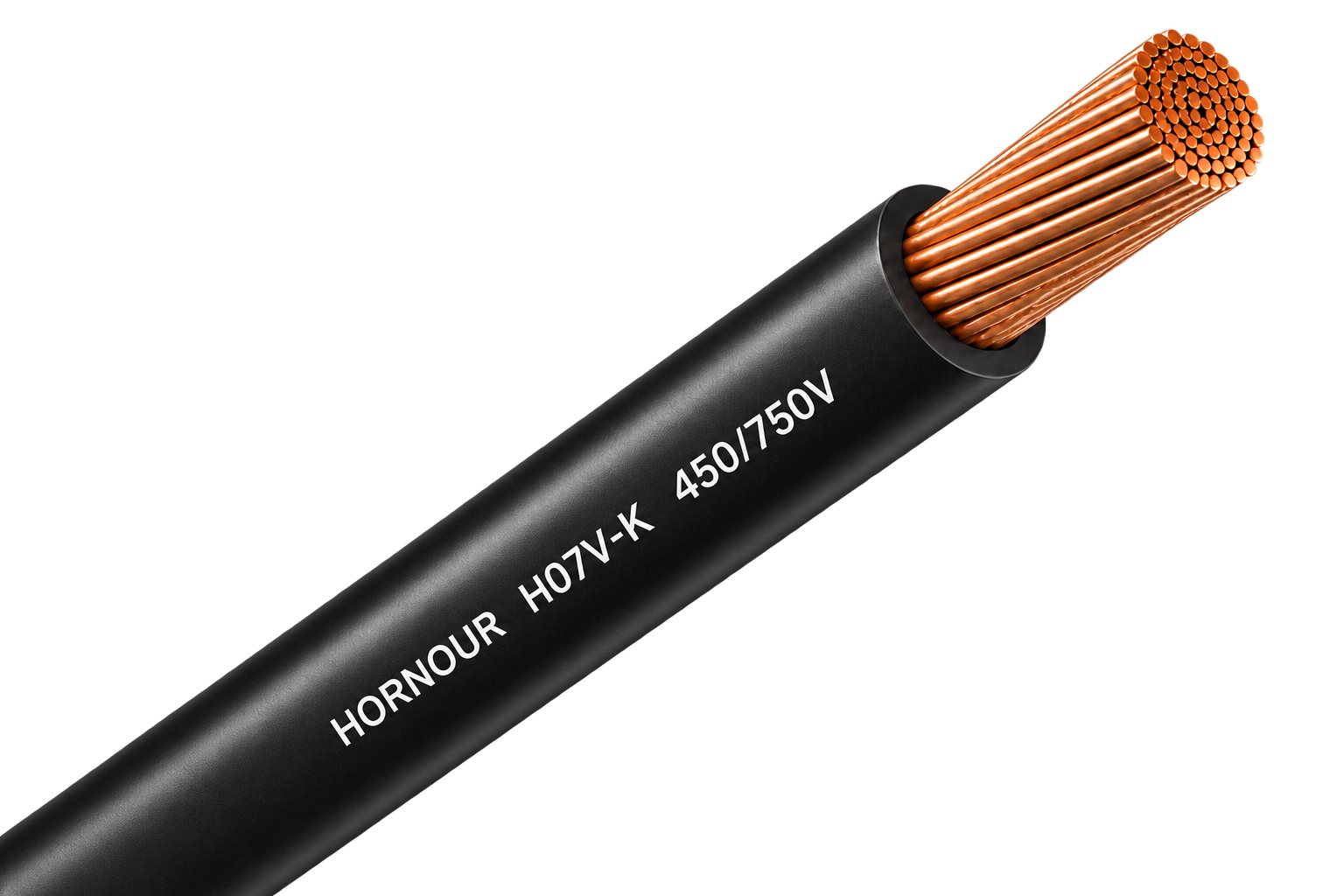
Flexible 450/750 V PVC wire for protected conduit, panel and grounding connections.
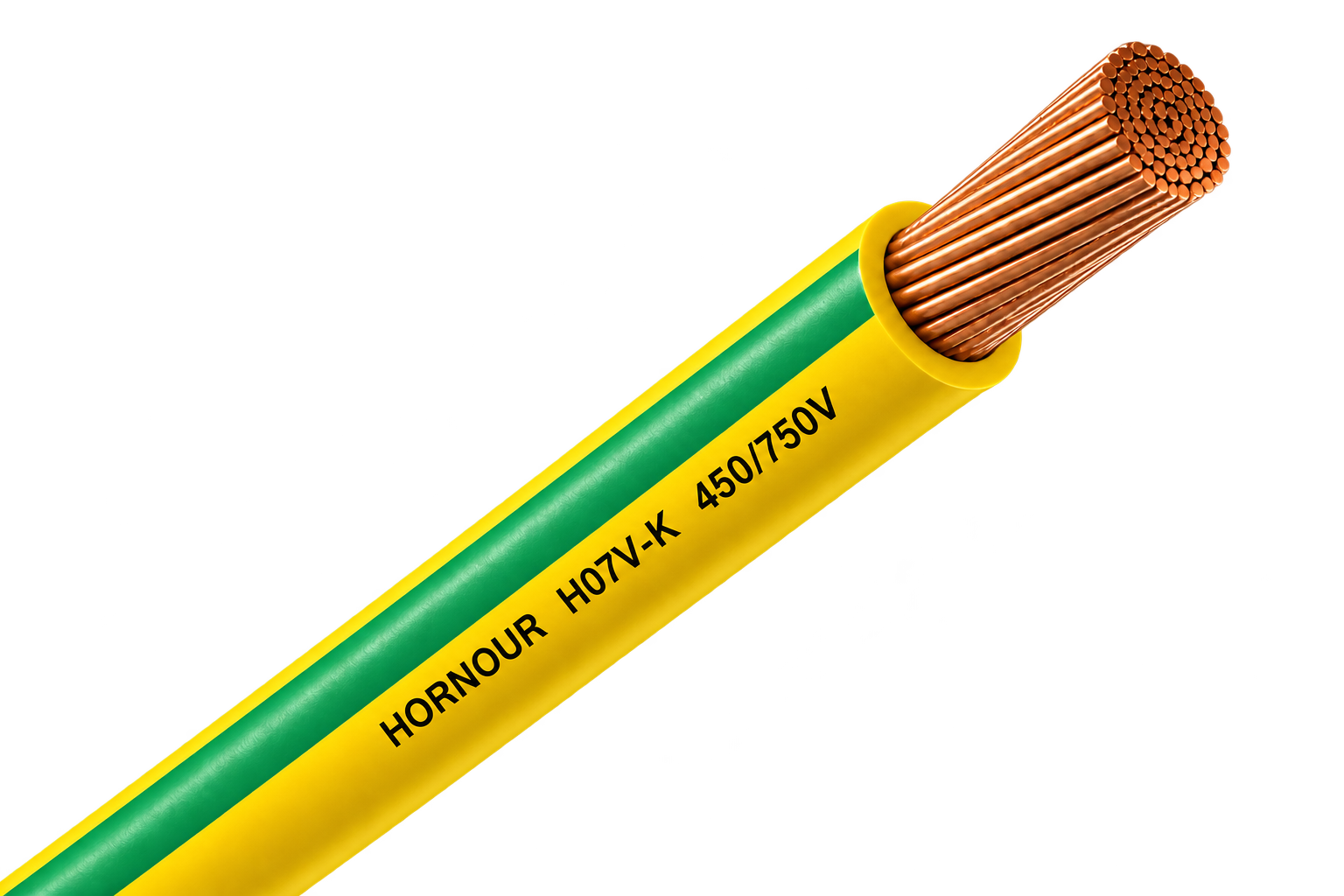
Green/yellow H07V-K Class 5 copper wire for protective-earth and equipotential-bonding connections in PV, ESS and electrical installations.
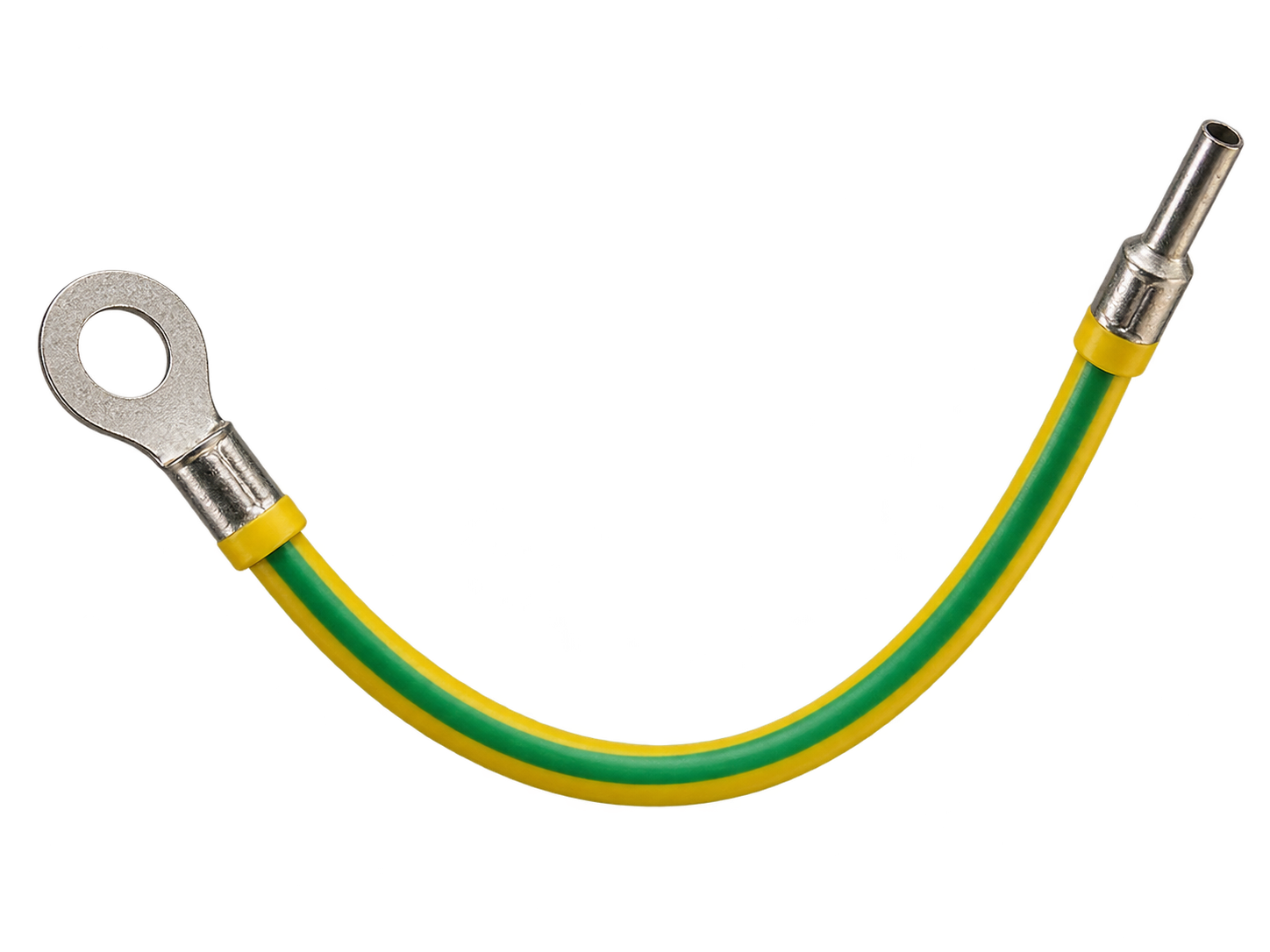
Green/yellow H07V-K grounding lead with factory-crimped ring / OT terminal for ready-to-install earthing and bonding connections.
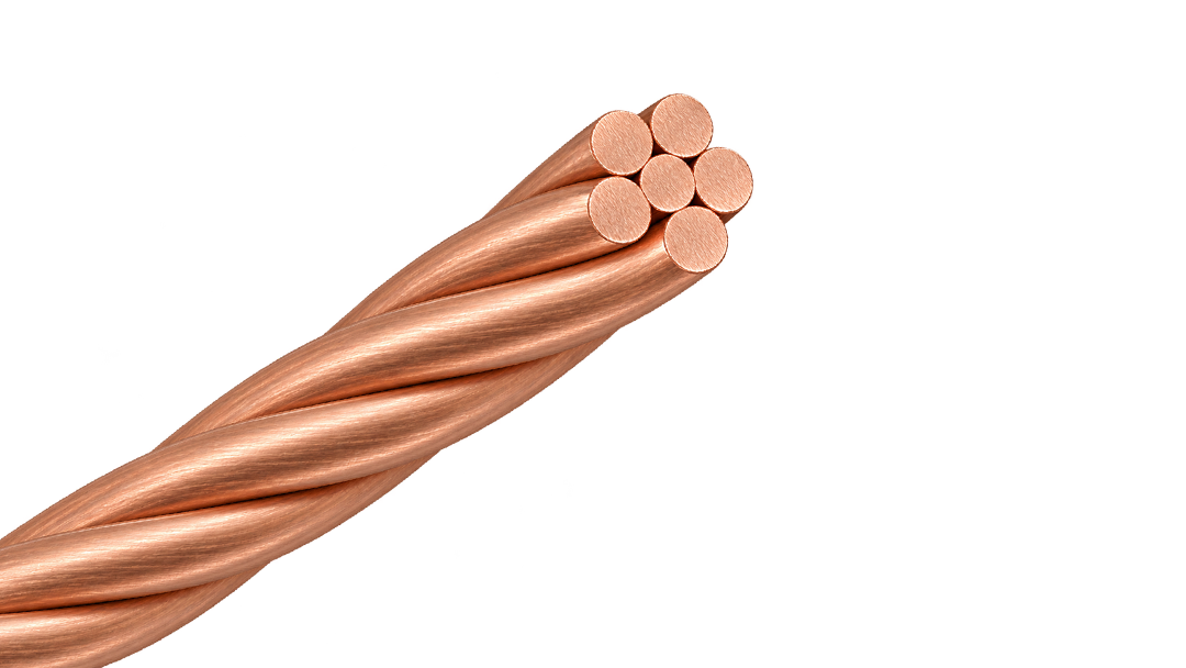
Bare Class 2 stranded copper conductor for earthing and equipotential bonding, available in 16–120 mm².
H1Z2Z2-K 1.5 kV DC solar cable with a nylon barrier beneath the outer sheath for PV routes that need a non-metallic physical defence against rodent damage.
H1Z2Z2-K 1.5 kV DC solar cable with external steel-wire armour for fixed PV routes exposed to severe rodent activity or mechanical damage.
H1Z2Z2-K 1.5 kV DC solar cable with a capsaicin-based rodent-deterrent sheath for PV routes where chemical protection is preferred over added armour.
Factory-terminated PV extension cable for controlled module, string and combiner-box connections.
Joined twin PV cable for orderly positive and negative string routing beneath solar modules.
Single-core PV cable for reliable DC wiring across rooftop and ground-mounted solar arrays.
Green/yellow H07V-K Class 5 copper wire for protective-earth and equipotential-bonding connections in PV, ESS and electrical installations.
Green/yellow H07V-K grounding lead with factory-crimped ring / OT terminal for ready-to-install earthing and bonding connections.
Bare Class 2 stranded copper conductor for earthing and equipotential bonding, available in 16–120 mm².
PVC-sheathed 300/500 V cable for fixed power and lighting circuits inside buildings and panels.
Solid 450/750 V PVC wire for stable fixed circuits in protected conduit and building installations.
Class 2 stranded 300/500 V PVC wire for fixed equipment and panel routes needing moderate flexibility.
Solid 300/500 V PVC wire for simple, stable fixed connections inside protected equipment and conduit.
Class 2 stranded 450/750 V PVC wire for protected fixed routes requiring easier pulling and forming.
300/500 V PVC-sheathed cable for fixed surface and flush-mounted installations in Finnish building wiring.
Flexible 300/500 V PVC wire for compact equipment, switchgear and control-panel connections.
Flexible 450/750 V PVC wire for protected conduit, panel and grounding connections.
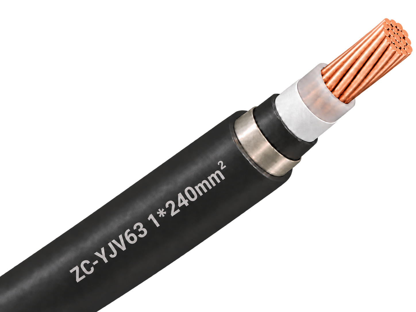
Single-core 1.8/3 kV copper XLPE cable with non-magnetic stainless-steel tape armour, PVC sheath and Category C flame-retardant construction for protected fixed power routes.
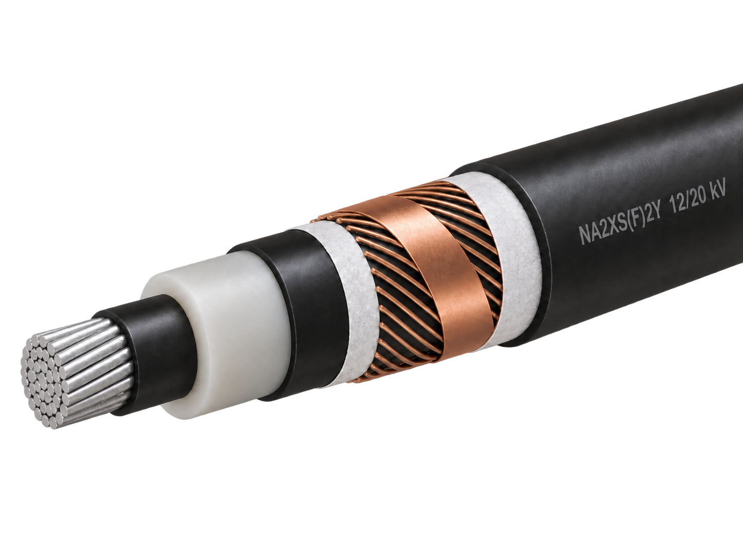
Aluminium XLPE medium-voltage cable with longitudinal water blocking for fixed distribution networks.
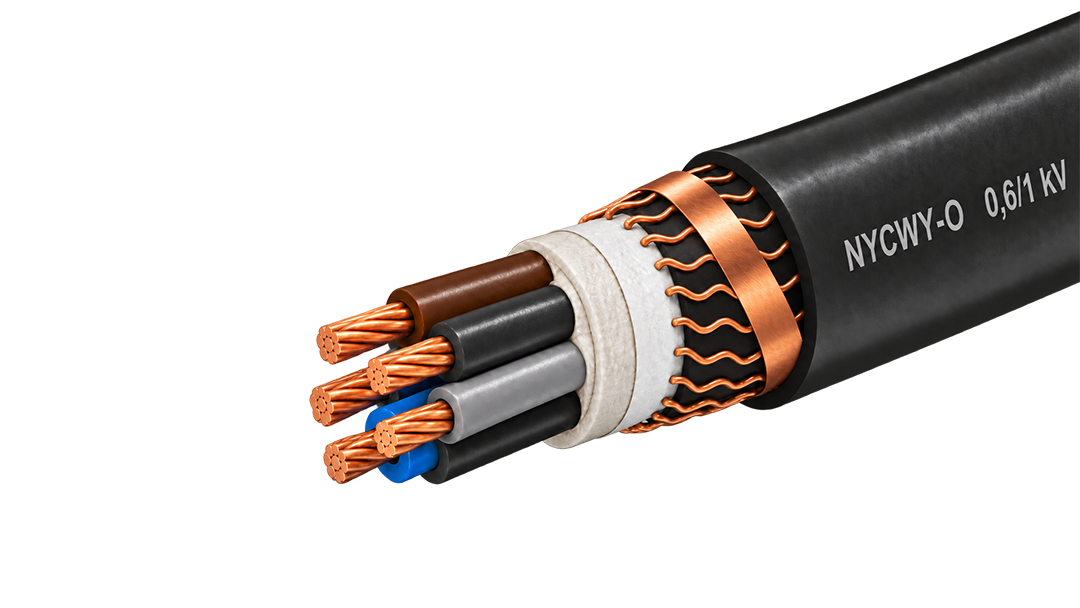
0.6/1 kV copper cable with a wave-laid concentric conductor for fixed distribution and service routes.
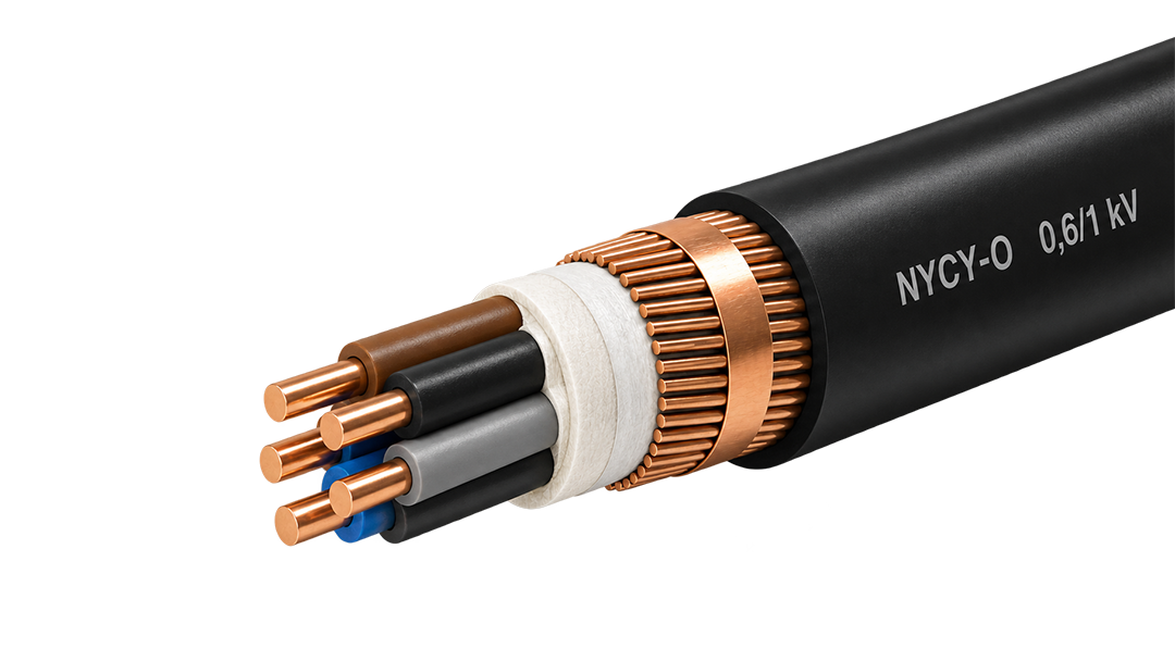
0.6/1 kV copper power cable with a concentric copper layer for service and distribution circuits.
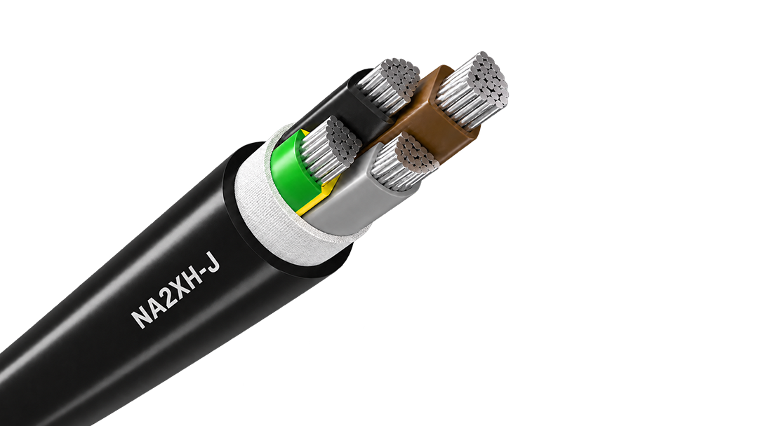
Aluminium halogen-free 0.6/1 kV cable for fire-conscious fixed distribution and long feeders.
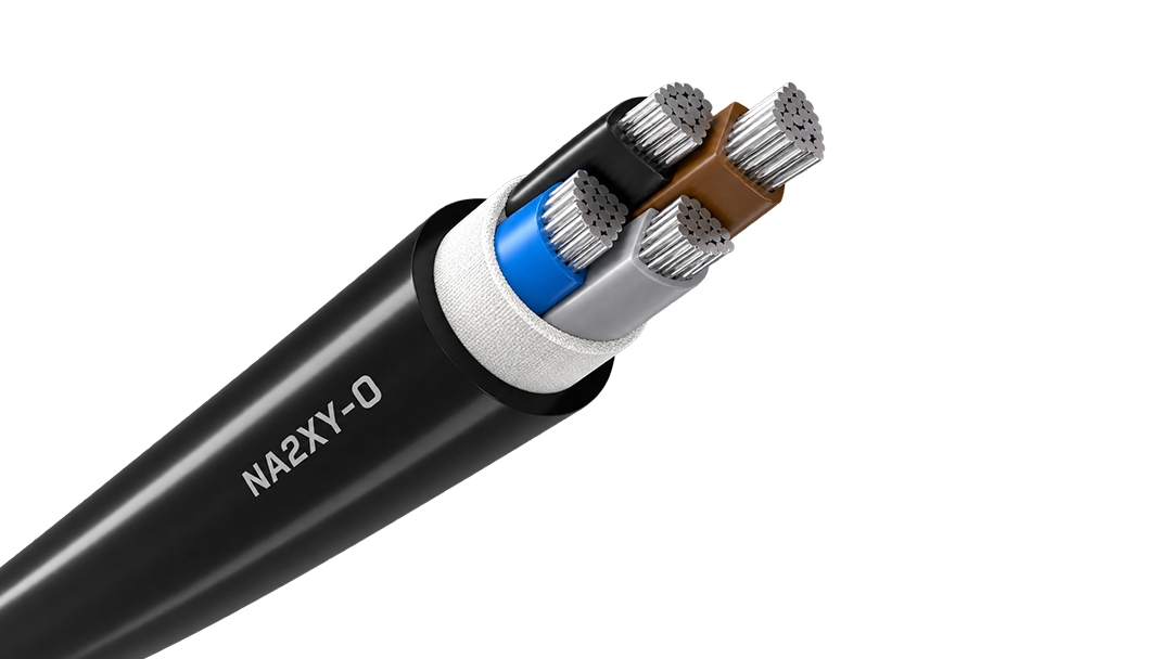
Aluminium XLPE power cable for economical fixed distribution, available in 0.6/1 kV and 1.8/3 kV constructions for long outdoor and buried routes.
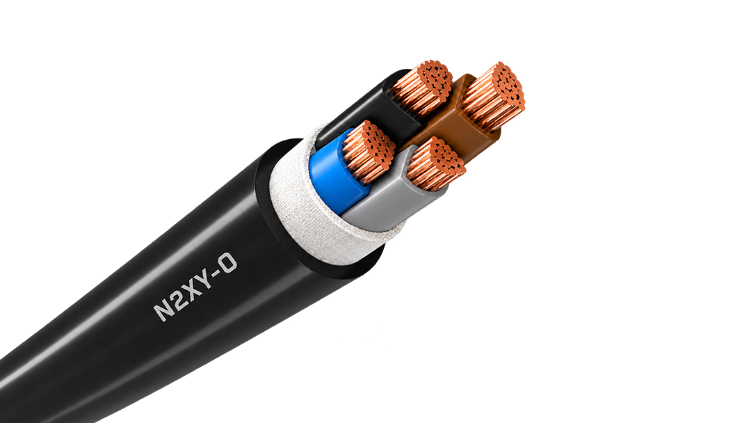
Copper XLPE 0.6/1 kV cable for demanding fixed feeders, outdoor routes and power distribution.
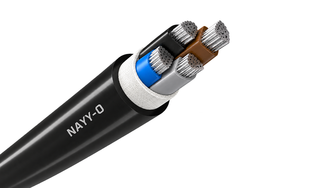
Aluminium 0.6/1 kV PVC cable for cost-conscious fixed distribution and long feeder routes.
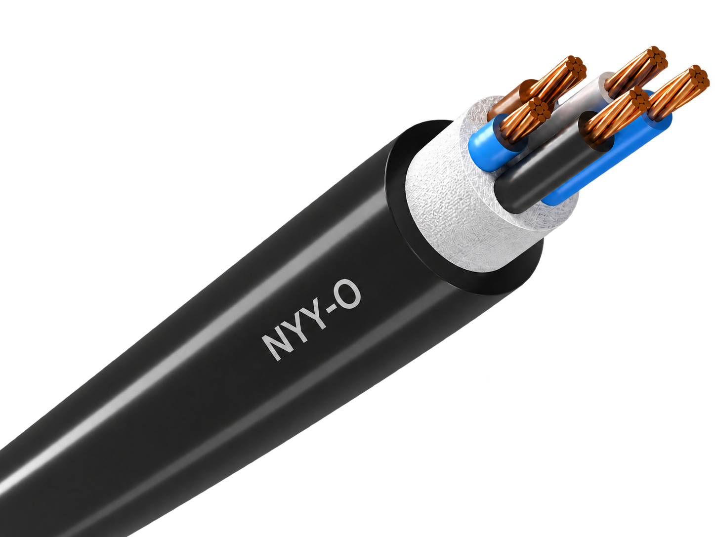
Robust 0.6/1 kV copper cable for economical fixed power distribution indoors, outdoors and underground.
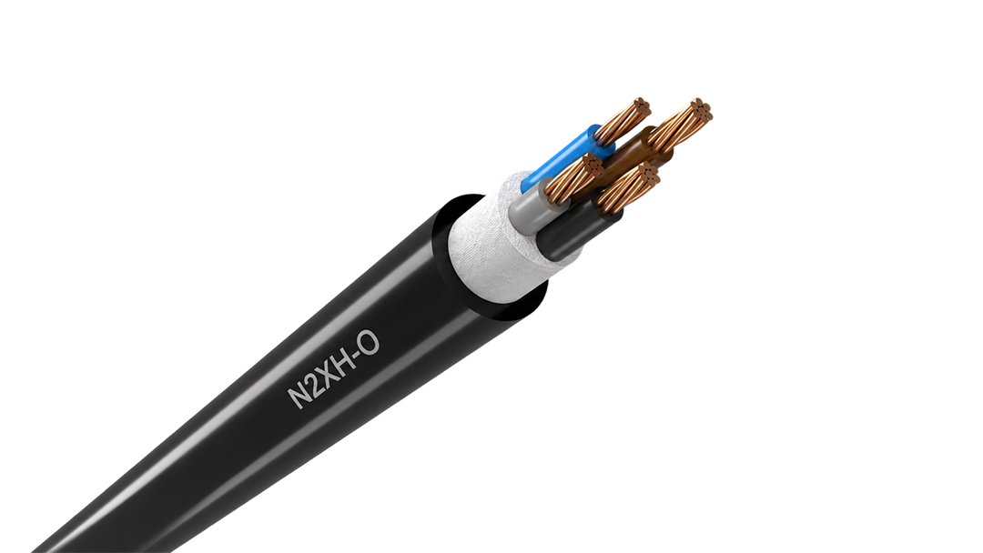
Low-smoke halogen-free 0.6/1 kV cable for fixed distribution in occupied and critical buildings.

hot search


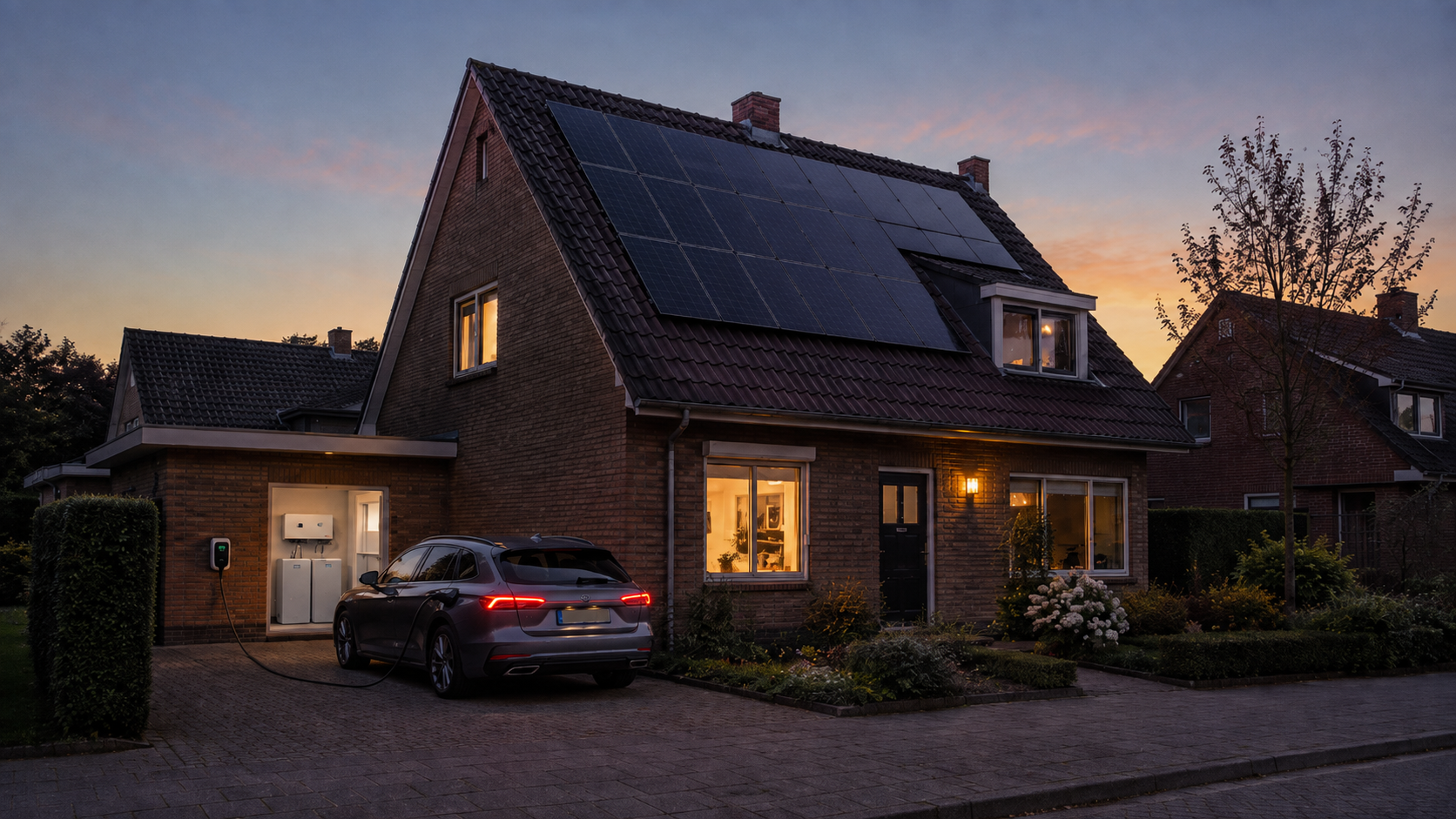
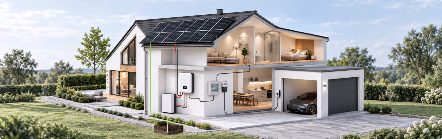
Connection Points in Residential Energy Systems
Solar cable
Flexible Installation cable
Grounding Cable
EV Charging
Extension Cable
Single-core PV cable for reliable DC wiring across rooftop and ground-mounted solar arrays.

UV & Ozone
Resistant

-40 ℃ ~ +90 ℃
Temperature Range

25+ Years
Service Life
| Voltage Rating | 1500 V DC |
| Conductor | Tinned copper, Class 5 |
| Insulation | XLPO |
| Sheath | XLPO |
| CPR Classification | B2ca to Eca |
| Applications | PV strings, inverter connection |
Flexible 300/500 V PVC wire for compact equipment, switchgear and control-panel connections.

Harmonised European H05V-K Design

Flame Retardant · IEC/EN 60332-1-2

Multiple Colours · Easy Circuit Identification
| Voltage Rating | 300/500 V |
| Conductor | Bare copper, Class 5 |
| Insulation | PVC |
| Size Range | 0.5–1.0 mm² |
| Max. Conductor Temp. | +70 °C |
| Applications | Equipment wiring, switchgear & control panels |
Green/yellow H07V-K Class 5 copper wire for protective-earth and equipotential-bonding connections in PV, ESS and electrical installations.

Protective Earth Identification

Flame Retardant · IEC/EN 60332-1-2

Harmonised H07V-K Design
| Voltage Rating | 450/750 V |
| Conductor | Bare copper, Class 5 |
| Insulation | PVC |
| Size Range | 1.5–240 mm² |
| Max. Conductor Temp. | +70 °C |
| Applications | Protective earthing & equipotential bonding |
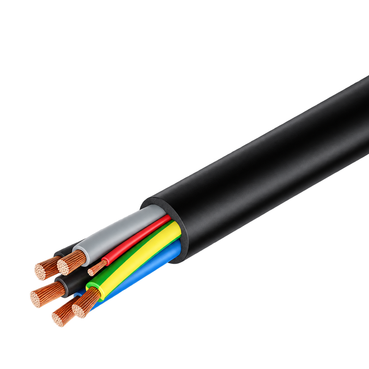
Flexible halogen-free AC charging cable for electric and plug-in hybrid vehicles.

Mode 2 & 3 AC Charging

Abrasion & Tear Resistant

Oil · UV · Ozone Resistant
| Voltage Rating | 450/750 V |
| Conductor | Bare copper, Class 5 |
| Insulation | Halogen-free EVI-2 |
| Outer Sheath | TPU/PUR, EVM-1 |
| Max. Conductor Temp. | +90 °C |
| Standard | EN 50620 / IEC 62893 |
Factory-terminated PV extension cable for controlled module, string and combiner-box connections.

UV & Ozone
Resistant

-40 ℃ ~ +90 ℃
Temperature Range

25+ Years
Service Life
| Voltage Rating | 1500 V DC |
| Conductor | Tinned copper, Class 5 |
| Insulation | XLPO |
| Sheath | XLPO |
| Base Cable CPR | Dca-s1a,d1,a1 |
| Applications | PV strings, inverter connection |


Cable selection reference for common residential PV, storage and electrical installation configurations
| Application | Connection | Recommendation | Installation |
|---|---|---|---|
| Rooftop PV | Module and string DC connection | H1Z2Z2-K Solar Cable | Roof · Outdoor |
| Rooftop PV | String extension | PV Extension Cable | Roof · Outdoor |
| Home Storage | Battery-to-inverter DC connection | ESS DC Cable | Indoor · Utility Area |
| AC Distribution | Inverter-to-distribution-board connection | LV AC Cable | Indoor |
| EV Charging | Distribution-board-to-wallbox connection | LV AC Cable | Indoor · Outdoor |
| Grounding System | Earthing Network | Earthing Cable | Indoor / Outdoor |
For commonly used PV modules, inverters, storage systems and connector interfaces.















Standard H1Z2Z2-K solar cable is designed to EN 50618 and IEC 62930 for photovoltaic DC applications. Related constructions may use the same electrical design basis, but the approval scope must still be checked for the exact product.
Twin cable, PV Extension assemblies and rodent-resistant versions are not automatically covered by the same certificates or CPR documents as standard H1Z2Z2-K. Each construction has to be checked separately. The current Capsaicin, Nylon Barrier and SWA versions do not carry a HORNOUR CPR claim.
For a connectorised PV Extension, the compliance of the base cable still applies to the cable itself, but it does not automatically classify or approve the complete finished assembly.
Grounding products have to be assessed according to their actual construction. The green/yellow H07V-K grounding wire uses the H07V-K cable construction to EN 50525-2-31, while HK25 is a bare Class 2 copper grounding conductor and should be specified according to its conductor construction and the project earthing design.
A pre-assembled grounding lead is different from the cable alone. EN 50525-2-31 applies to the H07V-K cable body, but once a lug or terminal is crimped onto it, the finished lead also depends on the terminal, crimp and completed configuration. Cable compliance therefore does not automatically approve the complete assembly.
Not automatically. A PV route can pass through several installation environments, and the cable requirements may change along the way.
Standard H1Z2Z2-K is intended for permanent PV DC wiring and is available with different water-resistance and CPR combinations. Current HORNOUR configurations include Eca and Dca with AD7 or AD8, while Cca is currently available with AD7.
Wet sections therefore need the required water-resistance level, mechanically exposed or ground-level sections may need additional protection, and sections entering buildings may have different fire requirements. Direct burial should not be assumed simply because a cable is suitable for outdoor PV use. Where mechanical exposure is significant, a protected route or an appropriate armoured construction should be considered.
PV cable sizing should consider more than operating current. Route length, voltage drop, ambient temperature, cable grouping, installation method and the allowable operating temperature all affect the final selection.
A cable that is adequate in free air may operate differently when several strings are tightly grouped, installed in conduit or routed through hotter sections of a roof. The current H1Z2Z2-K range is intended to allow conductor size to be selected around current, route length and grouping rather than using one size throughout the array.
A larger conductor may also be justified where reduced voltage drop and lower long-term I²R losses outweigh the additional cable cost.
Standard single-core H1Z2Z2-K gives the greatest routing flexibility and is suitable for normal module, string, combiner and inverter connections.
Twin cable is useful where positive and negative conductors follow the same repeated route, particularly below modules and along rooftop rows. Keeping both legs together improves cable management and makes the DC route easier to inspect and maintain.
Pre-assembled PV extensions are more suitable where a defined finished length and connector system can eliminate additional field termination.
Where practical, positive and negative string conductors should follow a coordinated route rather than creating unnecessary separation or large loops.
A PV connector should be treated as part of a complete connection system, not as a generic plug.
Connector manufacturer and model, cable size, contact, seal and mating interface must be compatible. Similar appearance or a general “MC4-compatible” description is not sufficient evidence that two connector systems can be mixed.
During field assembly, stripping length, contact size, crimp tooling, seal position and final connector engagement must follow the connector manufacturer’s instructions. The cable should not place mechanical tension on the connector.
Ingress protection also depends on correct assembly and mating. For the current Stäubli-equipped HORNOUR PV Extension, the stated IP65/IP68 protection applies when the connector is correctly assembled and mated; the unmated condition is different.